
Intro
This story comes about backwards from the way they usually do because first I bought an engine, and then went looking for a model. I ended up with a gorgeous example of a Nick Ziroli 1/5th scale PT-17 Stearman.
Dimensions
If you're unfamiliar with the model, it scales out to 2.4 inches to the foot (easy math, 12 ÷ 5 = 2.4 inches). This is why you'll often see 1/5th expressed as a ratio 1:2.4 and since the full scale aircraft length is 24 feet 3 inches (291 inches), and the wingspan is 32 feet 2 inches (385 inches), then this works out to 58.2 inches long by 77.2 inches in span.
Note; this Ziroli model is actually 59 inches long (the bit extra being added to the nose to help with balance) and 77 inches in span.
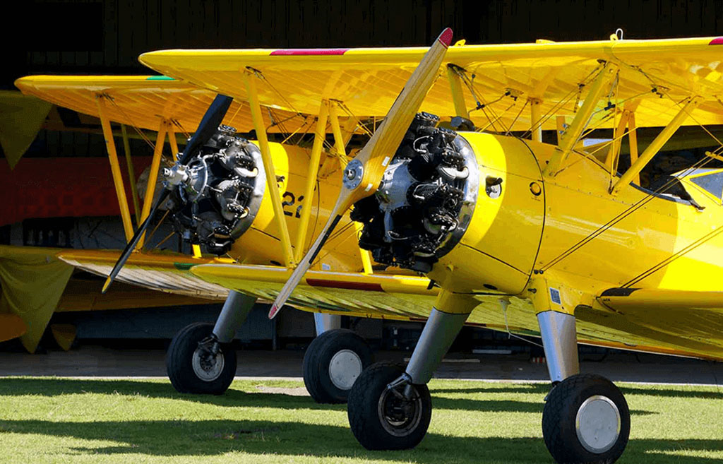
- Glistening in the sun, Stearmans painted in yellow Stits Poly-Fiber

Weight
Finished, they usually come in around 22-29 lbs. This maths out (due to a wing area of 1725 in² being about 12 ft²) for a wing loading of 29-38 oz/ft². And very importantly, these are great flying models because Nick took certain liberties with the dimensions.
For example, he increased the horizontal stab area, which ensures the model has a mild stall. And as I mentioned, he also lengthened the nose to help with balance.
Balance
Speaking to balance; the model shows a Quadra 35 on the plans. But in my experience, every one I've ever seen flew with considerably larger engines. Why? Not because they needed the horsepower because a 35cc is plenty. It's because they needed the nose weight. This, because even after Ziroli lengthened the nose a touch, most still took several pounds to balance.
nose weight
Power-wise I've seen these fly with engines ranging from a Quadra 52 to heavyweights like a Zenoah G-62. The latter is an especially well regarded engine capable of swinging a 22x8 at 6200RPM (thus, providing sparkling performance compared to the Q35 with an 18x8). Yet even with the Zenoah, the model had lead to help balance.
However, my major point is this; even when the engine weighed twice as much as the Quadra 35, the completed models all weighed pretty close to the same ready to fly regardless of the engine. Why? Simple, it's because everybody had to add ballast to the models (lead), especially those equipped with lighter engines! And by the time they were ballasted to the correct balance point, the AUW (all up weight) came in pretty similar. And yes, those with more detail, and/or especially glossy paint weighed more.
Note; these Nick Ziroli plans date back to well before the day of battery-powered ignition modules as fitted to engines these days. Instead, they all used magnetos, which are relatively heavy. Speaking of the plans, here's a link to the 1/5th scale Stearman plans if you want to order a set.
Minor point being, every modeler I know added ballast in the nose. Didn't matter if it was a Quadra 35, or a much heavier engine. The only difference being they used more lead with the lighter engines. But to bring the CG (center of gravity) into the proper range, most used a significantly larger displacement engine than necessary (heavier) to compensate for adding nose weight instead of using a ton of lead!
Put another way, this is a classic case of . . . six of one, half-dozen of the other!
Back in the day
Anyway, we're going to use this tidbit of information to our advantage. And by the way, if you're unfamiliar with the engine, below is a photo of the old classic. The finned bit on the front holds the magnet used to fire the magneto. With no battery to charge, the advantage is you'd never end the day due to a flat battery.
Note; as these were little industrial engines modified for modeling use, Dario Briseglia (the guy who promoted their use) left it to other entrepreneurs to create things like a cast alloy engine mount to encompass the stub of crankshaft sticking out the rear as well as mufflers.
One of the most popular being B&B Specialties, who innovated an ingenious spring starter for the engine similar to that used by a Cox engine. Just wind it backwards about 1/2 a turn and let go and it would fire up - very convenient!

- The engine which started the whole giant model airplane craze
Why cheat?
By the way, the obvious purpose of doing all this (larger stab and longer nose versus exact scale) being to ensure the models makes average pilots look good. Speaking of which, I've been flying +50 years (and am a fairly decent stick), but nevertheless I feel no shame in being called an 'average pilot' because it describes me perfectly!
Thus, I'm glad for Ziroli's foresight in increasing the stab area to make for gentler stalls and stretching the nose a bit! And one thing is for sure; you'll never find anyone who says Ziroli models don't fly well.
So here's how it all went down.
Background info
So I began this story with how I'd gotten the engine before the model. Here's how this developed. The other day (and entirely the fault of a good customer), I delved into a wonderful thread about UMS radial engines titled:
You see, he'd called to order servos for a Warbird Models 98 in F8F Bearcat. And as the chinwag progressed (and as I usually do), I inquired how he planned to power his model.
On Selecting servos
The engine being used is important information from my perspective because it gives me an idea of the expected level of flight performance. This, unsurprisingly, affects the servo decision because a more powerful engine usually means faster, which calls for more servo.
Similarly, I quiz a pilot regarding flight expectations because one pilot may fly a Cub in a perfectly scale-like manner whilst another will fly it like he stole it. The latter pilot, even if he's flying the exact same model at the same weight, will be safer and happier with stronger servos versus the guy who flies it like a little old lady.
On buying a radial
Anyway, as he began sharing details about his engine of choice, a UMS 9-115 radial engine, I became excited. This, because I'm totally queer for engines. So I began getting enthused for his project the more we talked. This, not so much for the model, but for the engine. In fact, when we hung up, I noted the time and a whole hour had gone by!
So once we got off the phone, I dug through the UMS engine-thread and very quickly, it was game, set, match. I had fallen in love! In love is code for . . . I had to have one!
Honestly, I couldn't resist and after consulting with Lynn, I immediately ordered one from Adrian Ciulei of CH-Ignitions (south Florida). As for the model number, the 9-115 is straightforward; it stands for 9-cylinders displacing 115cc, or a touch under 13cc per cylinder. What do these engines look like?
Well, I stole this image off Adrian's website . . . is this a thing of beauty, or what?
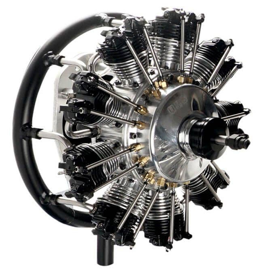
- A gorgeous example of the engine maker's art, the UMS 9-115
Why a radial?
So why did I want a radial engine? Sorry, this can't possibly be explained . . . I just did. And it's my good fortune to be married to a gal who understands my obsessions are part of what makes me tick. Best of all, she doesn't object to these occasional flights of fancy. Next problem? In what to install it?
On selecting a model
First, my pal's Bearcat is a lovely model, but a) they're bigger than I want to deal with, and b) I don't have time to build one. Added to which, c) I wanted a model in which I could see the engine as well as hear it (meaning not cowled in). An added factor is, d) these engines have exposed valve trains and the instructions call for lubing before the first flight of the day. Exposed rockers makes this task easier.
Anyway, the answer soon resolved itself because another pal (Josh Harel) with whom I'd discussed ordering the engine called me not ten minutes after we hung up. This, to ask if I'd seen the 1/5th scale Ziroli PT-17 listed as being for sale on one of the forums. And for what it's worth, his chops include building a Flair quarter scale Stearman and powering it with the lovely Robart radial.
- A sweet quarter scale Flair Stearman equipped with Robart radial
Best part of this 1/5th Ziroli Stearman aside from being gorgeous? Believe it or not, that the model was nearby in Ocala (about an hour and a half up the road), we're talking about a known great flying model, one which would expose the engine in all its glory, and it's nearby?
Honestly? This is like hitting the trifecta, or put another way, kismet at play . . . like it's meant to be!
On the stars aligning
Over the years, I've seen several of these 1/5th scale Ziroli Stearman models. Never flew one (could have, had I asked, I suspect). And the one thing in common is they all flew well regardless of engine or pilot. Anyway, finding one for sale nearby was a pure stroke of luck, agreed? Added to which, I'd long entertained hopes of owning one of Nick Ziroli's 1/5th scale Stearman models.
Doubly fortunate because until now, somehow the stars had never aligned for me to own one. Oh, and proof I'm into the aircraft is the military Great Planes PT-17 Stearman I have stashed away in its box. Unfortunately, this ARF at 72 inches vs 77 inches is a fair bit smaller, like maybe for a 20cc engine.

- Discontinued 72 inch wingspan Great Planes Stearman
Anyway, and circling back to the stars . . . they were about to align! This, because I reached out to the seller, and sight unseen, we struck a deal (good photos). We agreed to meet for the exchange and here's the latest addition to the fleet!
It's a truly lovely example of a 77 inch wingspan Ziroli PT-17 covered in fabric (Oracover) and modeled after a Navy example (yellow fuselage versus the usual Army blue). This example is powered by a DLE 35RA gasser engine.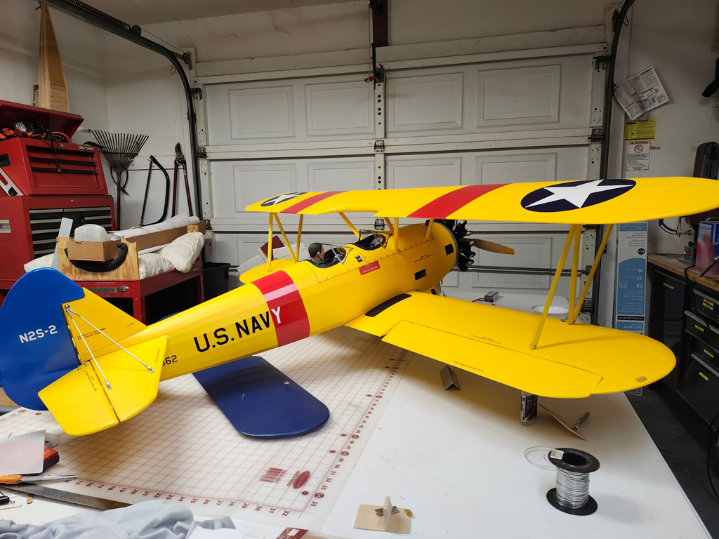
- Gorgeous Zirolli PT-17 by master builder John LaBelle of Ocala, FL
As you can see, it's finished as the US Navy's N2S-2 standard primary trainer. This was the aircraft used in NAS Pensacola for getting young pilots ready to fight in WWII. NAS means Naval Air Station, so we're talking about the US Navy base in Pensacola, Florida.
Note; the PT in PT-17 is short for primary trainer. This versus intermediate or advanced trainer. Anyway, the Stearman is the initial tool the US Navy used for making pilots, or naval aviators.
What's in a name?
Officially the Stearman Model 75, these are aka Boeing-Stearman (because Boeing had acquired Stearman in 1934) but also as Kaydet (Canada), N2S-2 (US Navy), and PT-17 (US Army) . . . if it served.
By 'served' meaning if it never entered ours or an allies' military inventory, then they're known simply as a Stearman. However, all refer to basically the same thing (with some variation in engines). To learn more, turn to this WikiPedia link.
Note; all article links open in a new window so you don't lose your place here.
Engines
Anyway, like I said, the deal with John was quickly struck and we agreed on a place to meet. Unfortunately, once I laid eyes on John's Stearman I immediately formed the judgement there was no way in heck it would work out as a platform. Why not?
Simple, because the UMS goes a touch over 9lbs while the DLE 35RA in the Strearman weighed 2lbs 10oz. Fortunately, there's more to the story or this would be the end of things!
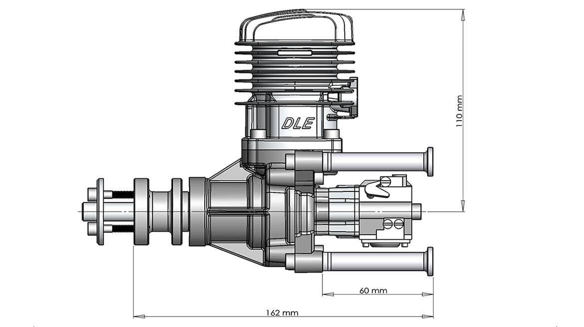
- I just knew (instantly) this wasn't going to work
Thing is, after putting him to the bother of driving to meet up with me to make the transaction, there was no way in Hell 'I' was going to be the guy backing out of the deal. So I swallowed hard, and bought it anyway.
And boy, am I'm glad I did! Let's examine why I was mistaken because as I've discovered over the years, I usually learn more from my mistakes than from my successes!
LaBelle's Ziroli Stearman
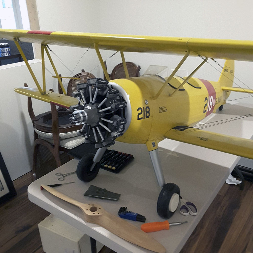
Operating on the assumption you're unfamiliar with the model, the 1/5th scale Stearman is physically a rather nice match to the baby 9-cylinder engine. For example, the Williams Bros dummy on the nose at 9-3/4" diameter vs 10-1/4" for the UMS 9-115. Basically, this little rascal is nearly perfectly scaled for the model.
And to be honest, it pains me in some ways to remove the dummy radial because John did such a nice job of building it that if he doesn't want to keep it, I may mount it to a piece of oak with a nicely routed edge. After being varnished, I figure to re-mount it there (almost like a trophy) to hang on the workshop wall for display.

- Lovingly built and detailed Williams Brothers dummy
Recapping, seeing the model in person for the first time left me with no question in my mind, the mass of the engine would simply be too great for this Stearman model. However, after I said this to John, he said I was wrong about the engine being too heavy. Said it would end up weighing similar to what it weighs with the DLE 35RA. More later.
This was important because finding the next size up Ziroli Stearman would result in a lower wing loading but overall a considerably larger and heavier model. This brings up another factor, which is my lower back. Not to delve deeply in my shortcomings (of which are many), quite frankly, I've reached a stage in life where between my lower back and my right shoulder (torn tendon), they have combined to no longer let me want to deal with larger/heavier models.
Bottom line? The larger Stearman was a non-starter . . . even if I had had one readily available! Time for plan B.
Plan B
So plan B came into play and I picked up a Flex Innovations 70cc Mamba from a pal in Jacksonville. My friend Craig Williams was basically tired of it and made me a good deal.
My thinking being; while it too had a 77 inch wingspan, with a much longer tail moment (plus aft mounted servos), the model would be better suited to carrying the load of a 9lb engine.
Anyway, if you're unfamiliar with the aircraft, she's an absolute beauty!

- Flex Innovations Mamba 70cc was a candidate for the engine
By the way, while not widely recognized as such, the Flex Innovations Mamba 70cc is also a scale model, but of the Pitts Model 12 (aka Macho Stinker). And because it's equipped with a Vedeneyev M14P, a Russian nine-cylinder radial, then it would be a nice match for the UMS 9-115 radial engine.
And for the curious, this photo shows how the length of the two 77in span fuselages compare. The difference is striking. However kindly overlook the sorry state of affairs (e.g. the mess in my shop). I promise this is not normal.
Anyway, and as you can see, they're a lot different length-wise for having the same wingspan!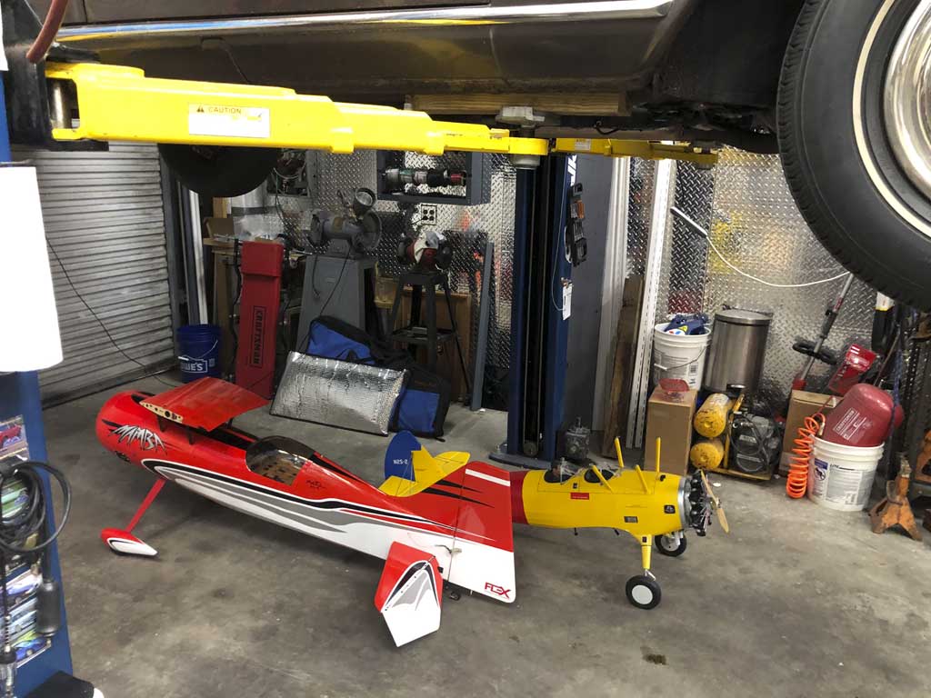
- Ziroli Stearman is dwarfed by the Flex 70cc Mamba
Enter the forum
Meanwhile, I had made a comment (basically introducing myself) within the UMS rabbit hole thread on the forum. To my surprise, the OP (the Original Poster, e.g. Aaron Hubbard, the guy who 'owns' the thread) kindly responded, with . . .
Welcome to the forum John. I have to add weight to most of my Stearman tails
to balance my fleet of heavy radial powered bi-planes (which are my favorite
radial mounts). Balance the Mamba with tail weight if necessary. The plane
will fly fine. Landings need to be ginger with weighted tails though. The gear
is vulnerable. Just my 2 cents for what its worth. Aaron, aka Hyjinx
. . . and just like that, I learned of someone using a radial on their Stearman - yippee!
Hmmm, could my initial judgement regarding the 9-115 being too much for the model be mistaken? Would it actually be possible to use this baby radial on the 1/5th scale Ziroli Stearman after all?
Well, as it turns out, the answer is, yes - but - as usual, the Devil is in the details!
Anyway, Hyjinx subsequently (and still on the subject of mounting the UMS radial on my Stearman), shared a photo showing a chunk of lead, which he'd bolted to the tail feathers of his 1/5th Stearman models. This, of course, being to counteract the mass of the engine so as to make it balance.
Hmmm . . . now my little gray cells have become quite agitated at the prospects!
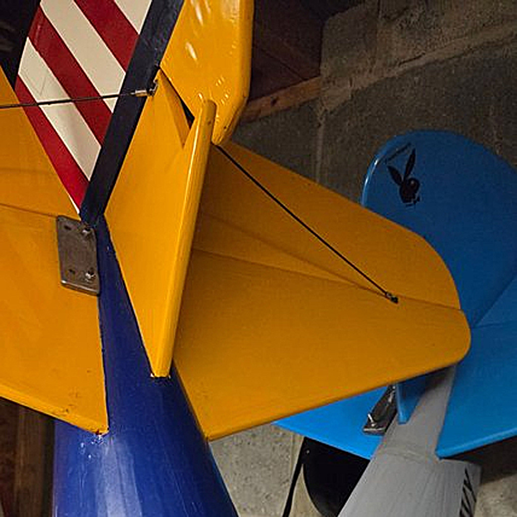
- Hyjinx's photo of the lead attached to balance the radial on his Great Planes Stearman
Williams Brothers dummy radial
Anyway, this next photo shows why I have been Jones-ing to install the UMS 9-115. As you can see, the Williams Brothers dummy hiding the DLE35 is a dead ringer (size-wise) for the UMS radial engine. Honestly? They're within a whisker of being the same size!
- Hard to discern from this photo, but these two are dead nuts size-wise
The trick
As always, retrofitting one engine for another means ensuring the CG of the model remains unchanged. For the UMS, this would involve more than removing the dummy and the existing DLE35 because in ensuring the model balanced, John had incorporated loads of lead shot (set with epoxy) up front near the firewall (actually in front of the firewall). And not just near the firewall but also within the individual cylinders of the Williams Brothers dummy engine!
Anyway, removing same would be a bear. This quite likely involve stripping the covering and the balsa sheeting off the longerons to get it all out. Moreover, I was thinking of building another plywood firewall to back up this one. My thinking was to bring the exhaust ring to near contact with the fuselage to better simulate what happens with the full scale bird.
That, or ditching the exhaust ring altogether (this, in an attempt to shift the engine toward the rear as much as practical).
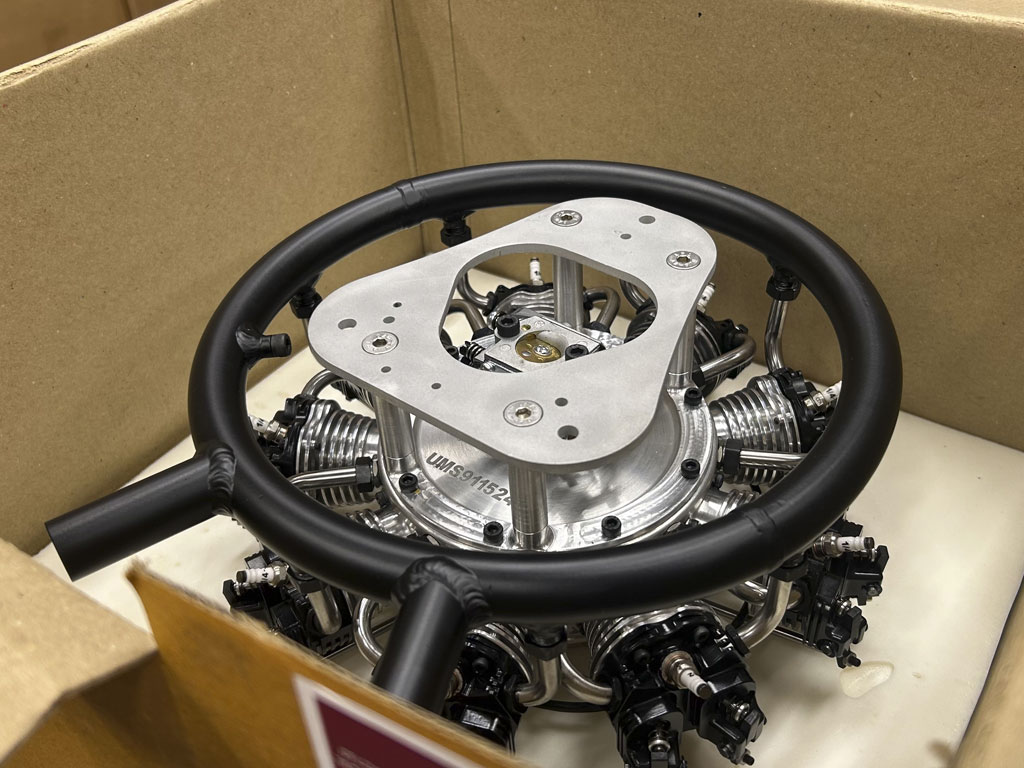
- Triangular UMS 9-115 engine mounting plate
Meanwhile, John and I are talking on the phone about how-to. He estimates 2-1/2 pounds of lead had been required to balance the model and because the DLE35 goes 1.19Kg with exhaust and ignition against 4.19Kg for the 9-115 in the same configuration, we're talking about an added 3Kg (6.6lbs). And accounting for the lead (6.6-2.5) equals about 4.1lbs difference. In theory. And he says it'll end up weighing nearly the same-same! His further idea is if the engine can be moved backwards a touch, then maybe it doesn't take any lead in the tail.
So it all depends on how far back we can shift the engine (thus, moving it closer to the scale location). John had told me from the get go his set of Ziroli plans were shot because mine had been the 3rd model he'd built off the same set of plans. Thus, he'd ordered another set, which he already had in hand when we met. Moreover, he was thinking the firewall could go back about 1-1/2 inches (the idea being to put the prop at the correct scale location).
Turns out this was really close to reality. John actually has it moved it back 1-5/8 inches, but I'm getting ahead of myself.
Anyway, like I said, the model is entirely too nice to butcher. Could the job be done and finished back so it looks nice again? Well, technically yes because it's covered in Oratex. That, and John has generously offered up what remains of a roll, which would be enough.
So the job is definitely within my skillset, but I just don't think I want to make the effort. Why not? Principally because I'm so covered up with work I haven't been flying in a coon's age. Sure I like to build but what I really love is flying! Taking on this job would see me not going out to fly for a while!
Brief interlude
And by the way, I'm not the first to visualize a radial on the front of a Stearman (not by a long shot). This next photo if of Ed Valls 1/5th scale Ziroli Stearman finished in the Tracey Curtis-Taylor Spirit of Artemis color scheme.
FYI, back in 2013 she flew her Stearman over the course of 8-weeks and covering some 8000 miles from Cape Town, South Africa to England. This link to WikiPedia has details if you're curious.
Anyway, Ed, not wanting to build yet another blue and yellow military Stearman opted for her gorgeous scheme - and - fitted his build with the smooth running OS MAX FR5-300 Sirius radial.
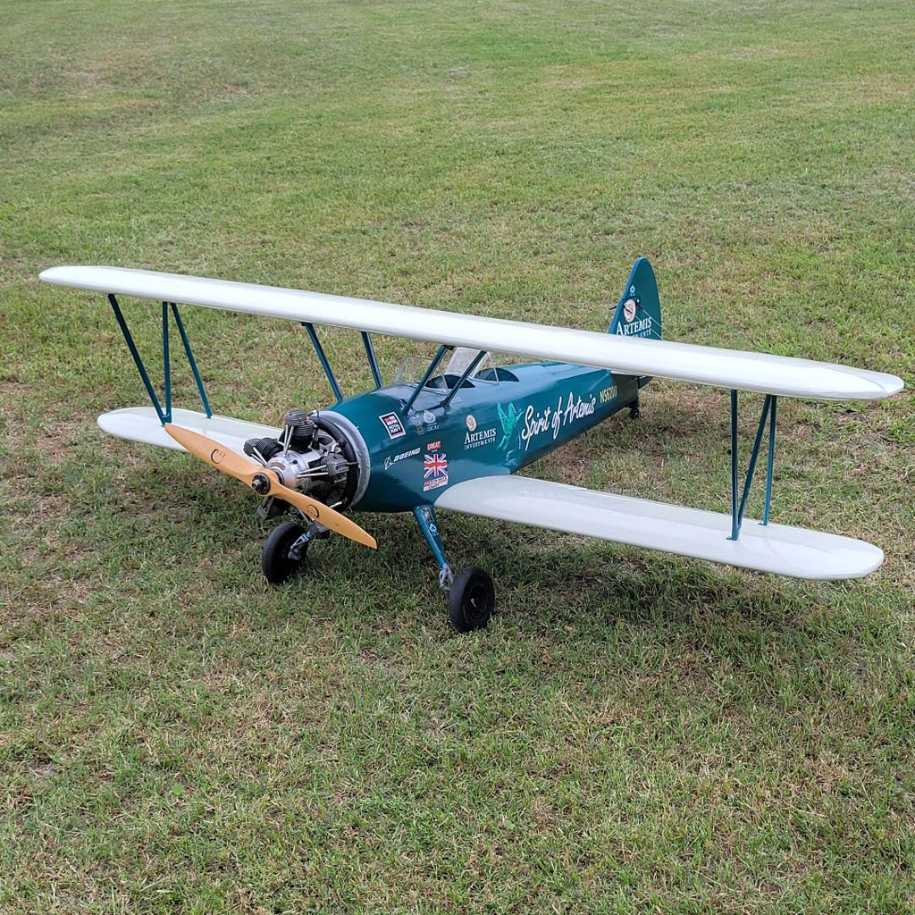
- OS MAX FR5-300 Sirius radial on Spirit of Artemis
Back to the story
So I was yakking with John LaBelle again the other day (remember, he's the fellow who built my Stearman). And recapping; I'm yearning to exchange the existing DLE35 for the UMS 9-115 radial because it would look bitchin' and sound righteous, to boot.
Frankly, this conversion has been preying on my mind. Anyway, I neither begged nor strong armed him into it, but to my great good fortune, he had caught my enthusiasm and (sort of) volunteered to undertake the engine swap.
Fast forward a few weeks, and a couple days ago we met in the parking lot of Graves RC. Me, having brought along the fuselage, engine, plus a set of my servos to upgrade the Hitec HS-645MG servos, which he'd originally installed. He brought the plans, also.

- Hitec installation being ditched for ProModeler in my Stearman
Let me be clear, John LaBelle is the builder. Me? I am merely the checkbook in all this because I bought the ready-to-fly model from him earlier in the year.
So here are a few more photos of this work of art before it gets modified. A nice touch is the placard calling out oil capacity. And guess what? When you remove the placard, you have access to the needle valve. Being a gasser means you don't fiddle with this much.
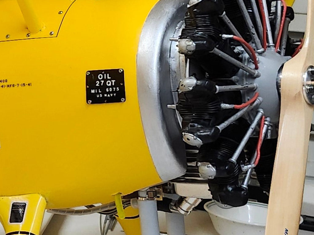
- LaBelle build of a Ziroli 1/5th scale Stearman
So in the real world after the model is flown a while (and the needle gets fine tuned), then you install the placard to cover up the opening and Bob's your uncle! You only remove the placard to adjust the needle on rare occasion (in my experience, I don't fiddle with needle valves very much).
Honestly? Covering the needle valve access with the oil placard is a really nice touch!
As should be obvious, John's a master builder and did a magnificent job of it - this was his third model off the same set of plans! Why three? Simple, because he really likes how it flies!
By this meaning it's a typically good handling Nick Ziroli design. One where he takes certain liberties in dimensions - but - where the end result is something that flies really well in the hands of the average guy. This, incidentally, defines me to a 'T' because while I'm a pretty good pilot, I'm still an average guy.
Landing gear struts
So now let me share with you a photo of the landing gear struts. Eyeball how nicely John incorporated Robart struts into the model versus the wire gear originally envisioned. Don't they look great?

- This shot shows how there's some serious craftsmanship involved
So the basic goal is to cut off what's already there (firewall forward) to allow fitment of the UMS engine. Problem is, will this work, or do we end up destroying this utterly lovely example of a Ziroli 1/5th scale Stearman?
What's more, there's the question; where does the engine really fit in relation to the forward fuselage? For that, I turned to Freddy's Stearman when it was at KEVB, where my Bonanza goes for annuals.
Note; this one never served in the war so while it's painted in US Army blue colors, it's referred to as a Stearman instead of as a PT-17.
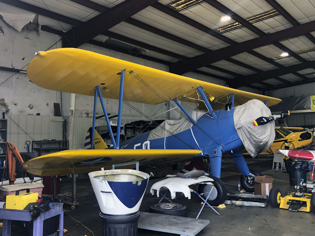
- Great looking aircraft, this full scale Stearman is a beauty
Surgery - creative destruction
In this next photo, I've fitted a #64 rubber band to the fuselage at the approximate location of the existing firewall. And I've propped the engine up in the approximate plane of alignment. Basically, this is what it would be like if the UMS 9-115 were mounted to the same firewall as the DLE35.
Note; with the UMS engine backplate in the same approximate location as that of the DLE35, the prop ends up about 5/8 inch further forward. But this location is actually a bit too far forward!
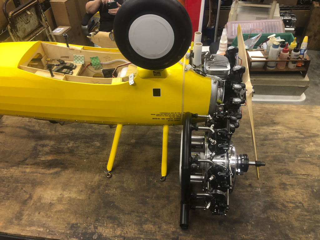
- The #64 rubber band marks approximate cut at existing firewall
Anyway, and after a fair bit of chin wagging both on the phone and in the parking lot the other day, John's of the opinion the firewall can actually be moved back 1-5/8 inches. This will them place the cylinders and prop in the correct scale location.
Note; as well as being quite a model builder, John is the former owner of Great Lakes, the manufacturer of the eponymous 21-IA biplane by the same name. As further background, this aircraft was first built from 1929–1933. Production was restarted 1973. After John bought the type certificate, he built 126 additional aircraft. That's a lot!

- Master modeler JohnLaBelle in the flesh
Anyway, John subsequently sold the business to the owners of the Waco type certificate. I don't believe they've built anywhere near as many of the aircraft as John LaBelle did. Worse, recently I learned they're struggling and may have actually gone bankrupt. Time will tell if this lovely aircraft has been lost to the world - sigh.
So all this by way of explaining that John knows a thing or two about aircraft, both model and full scale! Major point being, while I'm an experienced builder, I'm feeling like the grasshopper at the knee of the master. Minor point being, I'm going along with whatever John says, or wants to do.
So last night John shared a couple of progress photos. First, is this one section of forward part of the entire nose section behind the dummy. This, after removing the DLE35 engine 'and' after sawing off the dummy William Brothers radial engine.
As you can see, this bit is now setting on a scale. What for?
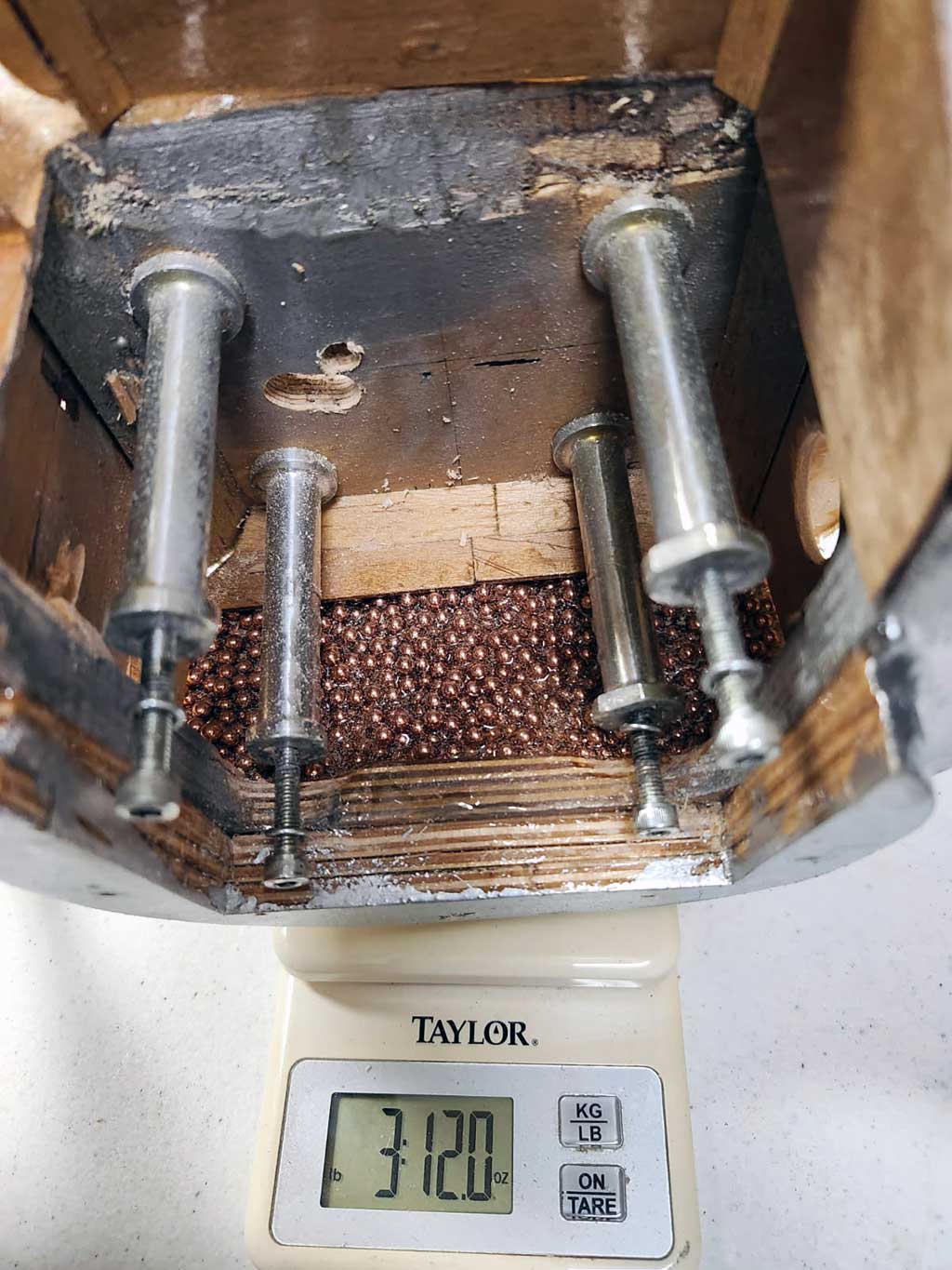
- Close up of forward fuse section sitting on a scale
The 'What for?' is to establish the weights of all components being removed. Anyway, as things stand, the total shed is now up to 9lbs 9oz.

- Engine, dummy, forward fuselage structure and lead shot
As this next photo shows, John has been taking note of the weights of what's been removed. This, for the purpose of documenting the total weight of everything that's come off/out of the model. And for reference, the UMS 9-115 engine (according to the manual) comes in at 4.19kg.
This is inclusive of the ignition, or 9lbs 3.5oz. To this we'll add an ignition battery amounting to 5-1/2oz. Net-net is going to be near zero! Maybe John's going to be right about total weight being nearly the same with the baby radial versus the DLE 35RA engine.
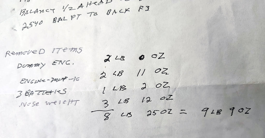
- Mass removed so far amounts to 9lbs 9oz
Note; included in the 9 pounds 9 ounces are the three avionics packs (the model had a battery backer and two flight packs plus a third pack for ignition. This last will be replaced by a single pack with a higher capacity since it'll be responsible for firing 9-plugs instead of one.
Oh, and instead of using two battery packs, my inclination is to use one receiver pack and two switches as insurance against switch failure, instead.
Surgery - reconstruction
Recapping; the plan is to add back some plywood and balsa structure upon which to attach the new engine.
Note; this is me using the royal 'we' because it's John who is doing all the work!
Anyway, John called last night excited that instead of 1/8-inch lite-ply as called out for on the plans, it turns out he'd actually used birch aircraft ply, instead. This is much stouter stuff, of course. This works in our favor!
So in this next photo we see the side view of the plans. John has cut back to just ahead of former-F3. Note the old school Quadra 35 engine depicted. This engine was state of the art back when Nick drew up these plans.
For what it's worth, most of these I've seen fly were powered by a Zenoah G-62 because the owner said it needed so much nose weight he'd rather use more engine than dead weight. Bodes well for what we're doing, eh?
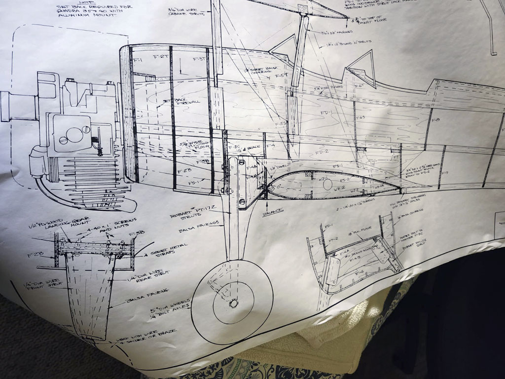
- Ziroli 1/5th scale Stearman side view plans
Next, eyeball the plan view of the fuselage because it makes this box-like plywood forward fuselage structure a bit more obvious. These models are stoutly built because back in the day, big thumpers were all that was available (and those things really shake).
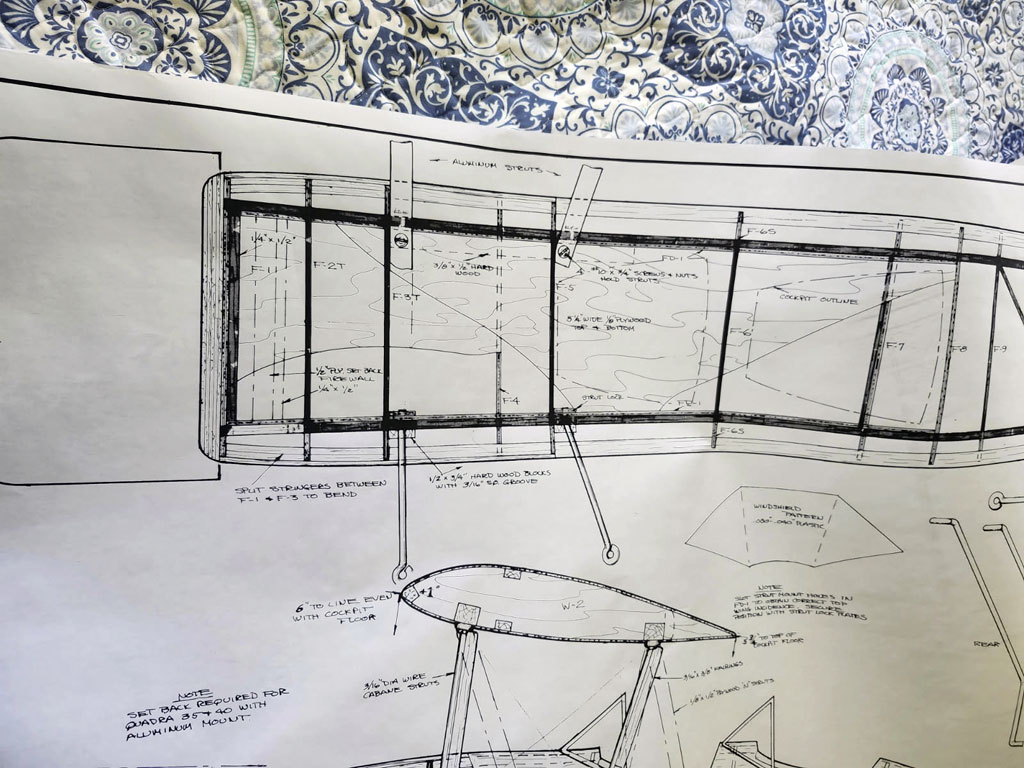
- Ziroli 1/5th scale Stearman plan view
center of gravity, part I
Anyway, because it's a 9-cylinder, it'll be a lot easier on the airframe than a paint shaker like either a Q-52 or a G-62. This, principally because it will run a lot smoother. So instead of one big power impulse, there are 9X as many much less forceful power impulses feeding back into the airframe!
And now let me make a confession; it's taken until 'now' for me to really begin to have faith this harebrained engine lash-up of a 115cc radial mated up to a 1/5th scale Ziroli Stearman is actually going to work out! What has now fully sold me on the idea? It's seeing how much weight came out. Let me explain.
As John argued from the beginning, the DLE 35RA with enough ballast weight to balance on the leading edge of the lower wing (as called out for on the plans) had gone 24lbs. So that's what we started off at. And FWIW, this is about average for one of these things no matter who builds it or how it's powered. Why?
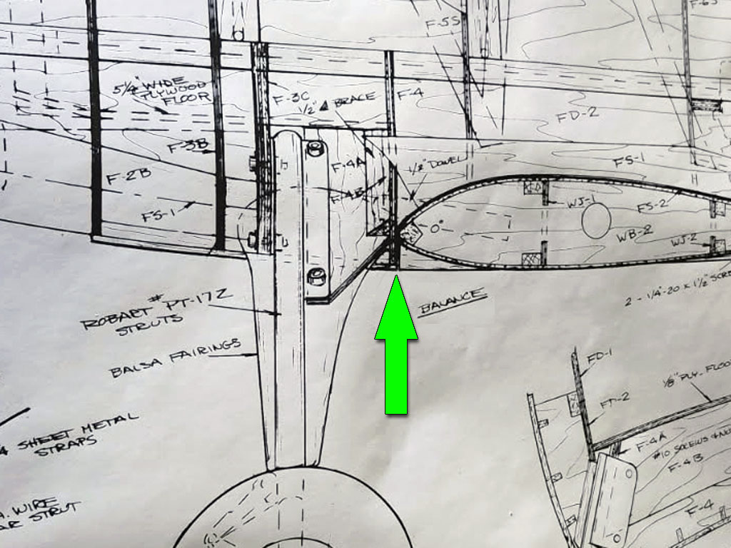
- CG is the former for the lower wing's leading edge
Aircraft designer Nick Ziroli called out the balance point at the lower wing's leading edge former. That's the flight proven point of about where they fly best. Moreover, whether you do it with a DLE 35RA or a Zenoah G-62, the AUW (all-up-weight) as John observed ends up about the same because the lighter engine has to be ballasted enough to offset the mass sitting behind the CG.
Major point being, my suspicion is this thing's going to again be near 24lbs again despite the significantly greater mass of the baby radial. But let's not put the cart ahead of the horse. The final weight determination will be made empirically, e.g. we'll weigh it when we're done (eventually).
So where are we now? Re-configuring the forward fuselage by chopping off the front end and existing firewall. This, to accept the replacement engine.
How a plan comes together
So once the fuselage has been cut flush at former-F3, this is what we're left with. All laid out before it on the workbench are all the parts of the structure, plus the DLE 35RA engine and muffler, the Williams Brother's dummy radial, plus assorted bits and bobs (ignition and batteries), which have been removed. Looks naked, doesn't it?
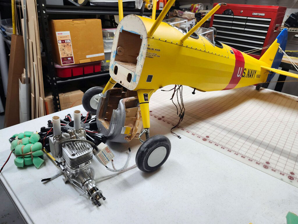
- Amounting to 9lbs 9oz are engine, fusleage structure, dummy, batteries, plus lead
In short, this is all the stuff, which add up to 9 pounds 9 ounce! In it's place will go the 9 pound 3 ounce radial engine, plus ignition and avionics batteries.
My guess is by the time we add in for the new firewall of 1/2 inch plywood, plus the fuel pump the engine needs to run, then we end up at about 25lbs, but we'll see.
Filler
So you may have noticed in the above photo the bright blue stuff on the firewall. It's filler. This next photo shows it better (before sanding). Anyway, it's just lightweight filler (a 2-part epoxy). It's mixed up at a ratio of 2:1 until it's a consistency of something like Bondo. Applied and sanded off, it'll smooth out the ugly!
Note; ignition module and 20 ounce fuel tank are just laying in place. John believes we can make way for a 24 ounce tank, but I'm inclined to maybe opt for a 16 ounce tank because these engines are reputed to be thrifty.
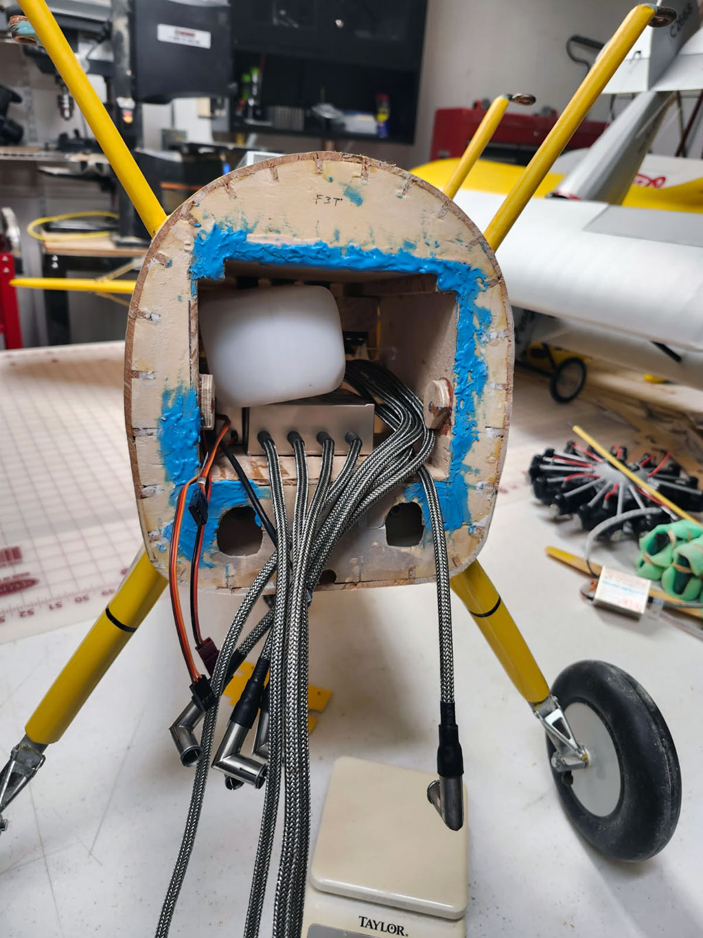
- The forward fuselage is a basic 1/8-inch plywood box
So according to John, sanding this stuff is easy. Says it's a lot like sanding foam. The product is offer by Stits (where it's principally used in full scale aviation) and is called SuperFil. Anyway, as you can see, it's bright blue somewhat similar to painter's tape.
This is what their website has to say about it . . .
It's an epoxy resin and an MDA-free hardener that allows us to ship it
as non-HAZMAT. We add microballoons and other high quality fillers to
achieve the peak of structural performance and lightness. SuperFil weighs
15 ounces per mixed Quart! Excellent for fillets or large holes, mixes at
the consistency of peanut butter.
. . . but because John swears by it, his recommendation was good enough for me! I ordered some for my shop right off Amazon.

- Stits SuperFil 2-part lightweight filler
Organization
Next up is making everything fit. So here's what John ended up doing . . . he made dividers. For this he used 1/8-inch lite-ply plus 3/8-inch balsa triangle stock to create rails so they could slide in from the wing opening after the firewall is attached and reinforced.
Note; all this will be fuel proofed.

- Dividers made of 1/8-inch lite-ply with balsa triangle stock rails
So here is everything dry fit together. Makes it easy to see what he has planned.
Fortunately the 15 inch long ignition leads allow the module to be placed fore/aft and still snake out to the cylinders.
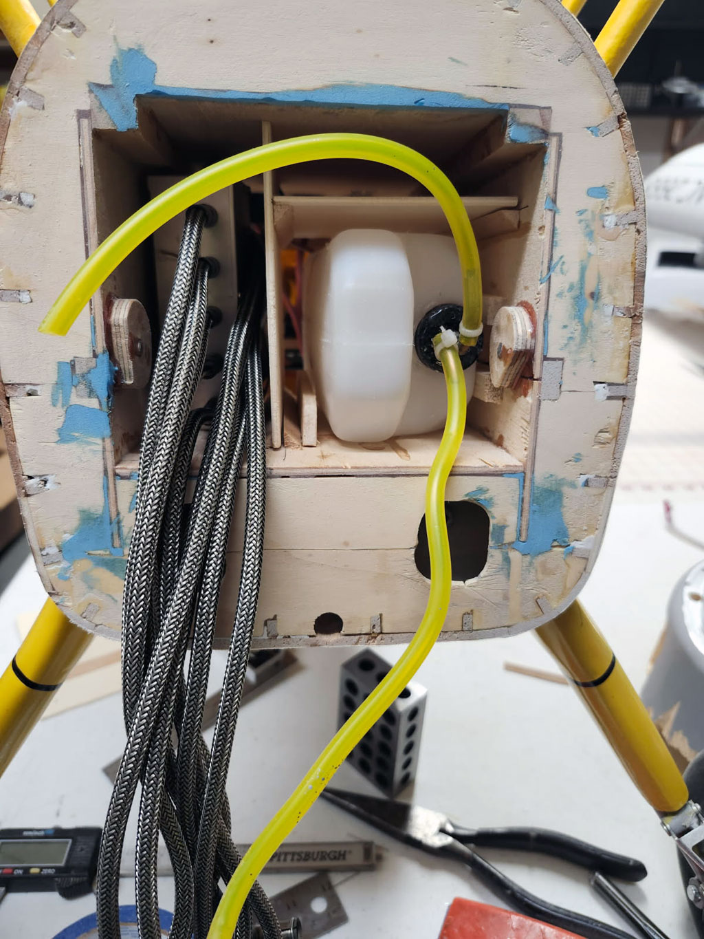
- Ignition module and fuel tank in place
Firewall
In this next photo we see how the engine mounting plate will align with the firewall. This piece is supplied by UMS and I feel it's a nice touch to include it with the engine because the usual is just a paper template. This is better!
So once positioned and held in place with blue painter's tape, the basic plan now is to double up 7-ply birch 1/4 inch aircraft ply to make a 1/2 inch thick firewall (14-plys) to fit into the box structure.
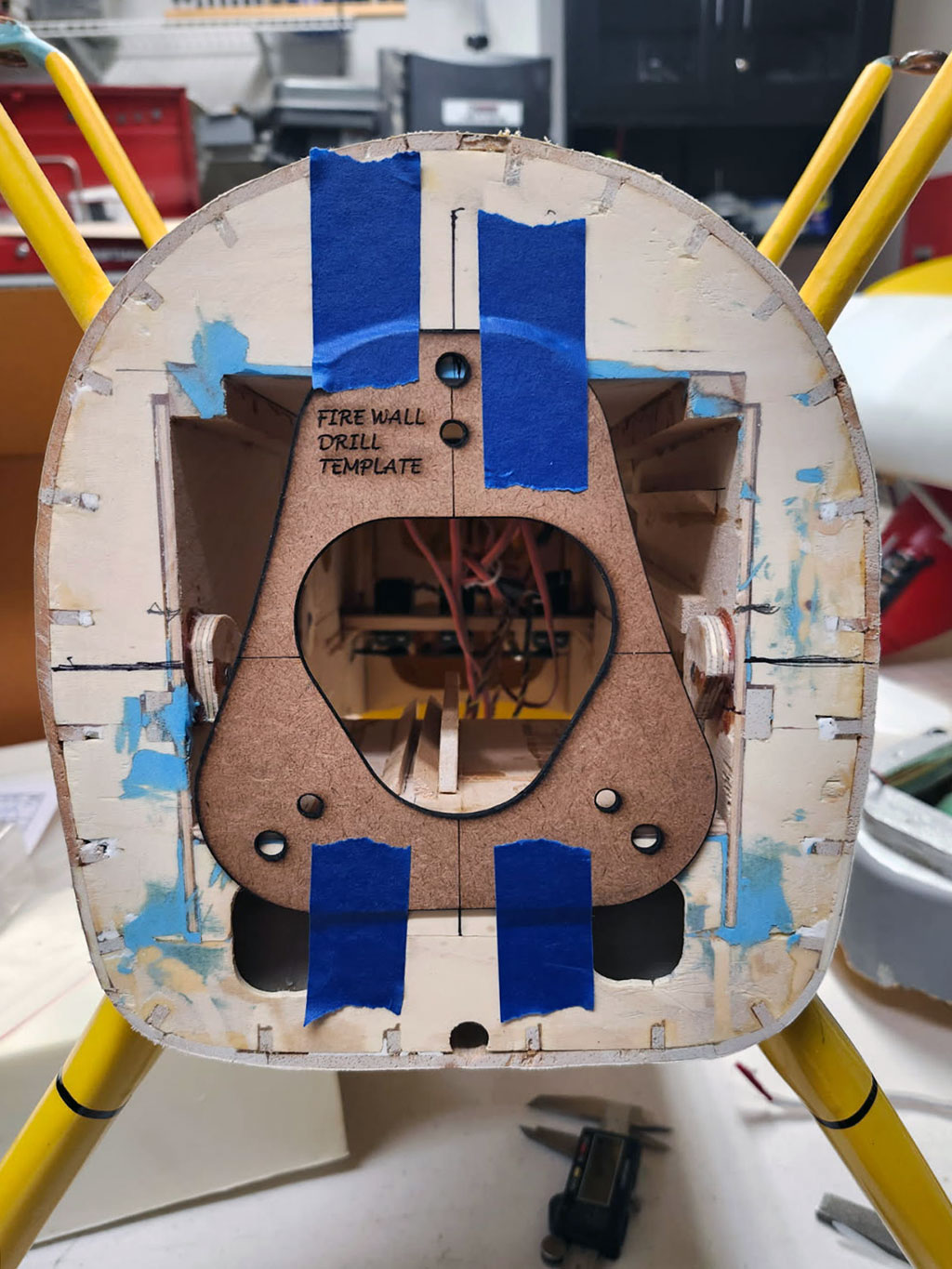
- Supplied with the engine, this nice wood template
Only thing is, using the three outer holes would be a clusterfuck because they interfere with the 1/8-inch aircraft plywood box. Fortunately, using the inner holes makes it dead nuts easy.
So the plan is to drill these out to allow using 1/4-20 mounting bolts to secure the engine. Once these holes are drilled out to permit using socket cap machine thread bolts going into t-nuts, we'll be in tall cotton.
Note; It's John's judgement (which which I fully concur) this will be adequate to secure the engine to the firewall. The firewall, incidentally, will be further reinforced on the inside of the box structure with triangle stock.
This brings up a question. Can we get to the mounting bolts? Short answer is yes, we can just snake a ball-end Allen driver in alongside cylinder #1 to reach the top-most engine mounting bolt. The other two mounting bolts are easier to reach because there's no cylinder blocking them.
Don't you love it when a plan comes together?

- Using a long Allen driver, we can sneak in to the mounting bolts
So now we're down to the firewall. It's relatively straightforward . . . an approximately square piece of plywood, but comprised of two layers of 1/4-inch birch aircraft plywood (the good stuff, 7-layers). So we end up 14-layers at 1/2-inch thick. This, to have plenty of surface area for attaching to the 1/8-inch plywood box structure.
As for the alloy engine mount, it gets secured with three I/4-20 x 3/4-inch socket cap machine-thread bolts going into T-nuts on the backside. But what's important is to take note of the ignition leads alongside the mount. These are only four of nine! Getting all 9 through is gonna be something of a challenge!
Note; the 3 tick-marks within the center area of the mount are for the throttle pushrod (favored solution, Sullivan Gold-N-Rod), plus fuel lines.

- Firewall comprised of two pieces of 1/4 inch thick 7-ply birch aircraft plywood
On the horns of a dilemma
So now we find ourselves with a dilemma - a somewhat intractable problem. To wit, how best to get through the front of the airplane structure with 9 spark plug leads without weakening it too much? Like we're talking about needing a substantial hole to get them through - and - we don't want to weaken the firewall.
Note; I'm not wanting to go through the middle of the alloy mount because this then exposes the inside of the aircraft to the fuel mix which inevitably stands off from the carburetor at part throttle. Big mess over time as it soaks into the wood despite our best effort to fuel proof the structure. Basically, I don't want to go there, and John agrees.
So John suggests we go down through the bottom edge of the box to make clearance for the leads. I'm not quite seeing it in my mind's eye (remember, we're on the phone because he's in Ocala whilst I'm in Sanford). Also, while it's just 70 miles away, every route is something of a goat rope (an 1:49 according to MapQuest). Saying I'd sooner fly in the Bonanza than make the drive, but I digress!
Anyway, he lays in a bit of painter's tape and sends me this photo.

- A bit of painter's tape marks the propossed cutout
On weakening the firewall
However, I'm concerned about cutting through the firewall itself. This, due to apprehension it weakens the firewall mounting (after all, the engine goes 9 pounds).
So next he dry fits the fireplace in position to help me better visualize things and sends another photo. This brings up another concern, the mess this will make.
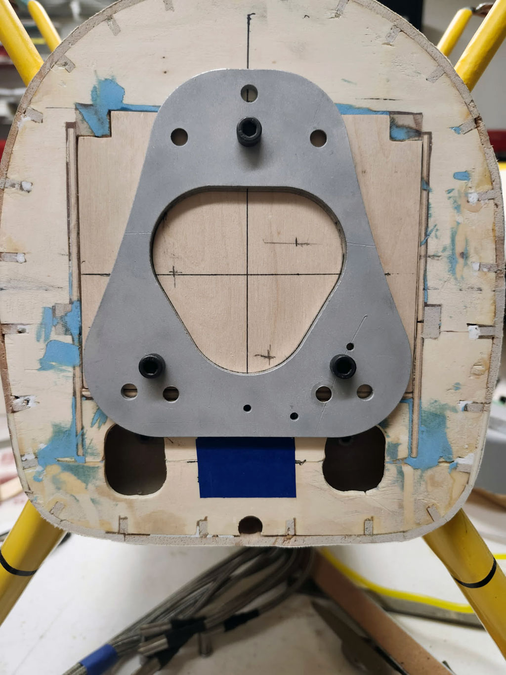
- Dry fitting the firewall in place helps me see what he has in mind
The drips
Anyway, and to be honest, I'm still not lovin' it. Why not? Beyond worry about weakening the firewall, now I'm thinking about how the carburetor will be immediately above those sweet RCEXL braided stainless steel leads. Thinking over time the spark plug leads will get repeatedly dripped on by premix.
Thing is, even at 40:1 gasoline-to-oil, while the gasoline will readily evaporate, the oil won't. Worse, it'll seep in between the braided sleeve and the rubber insulator and stay. End result? Before too long it'll be a sticky mess because the oil residue will attract dirt - yuk!
On reflection, John agrees and next he proposes going through the front upwards, instead. So remember, there are plusses and minuses to everything. The plus for this alternative is we don't touch the firewall because the leads will perforate the 1/8-inch box but then go around the firewall itself and come through former-F3. However, the minus (as he wryly observes), is having all the leads exit up high makes them very visible (and rather ugly).
Anyway, he places a piece of tape about where he thinks best, takes a picture and sends it over.

- Another piece of tape marking a propossed exit
What about on the sides?
Once I see what he means, and considering his point about all the leads exiting near the top being ugly, I then counter with how about on the sides? He doesn't see what I have in mind so after taking his photo into Photoshop, I modify it and show him this next photo; one hole for a set of 4-leads, and another hole for the remaining set of 5-leads! Sweet, eh?
This seems reasonable to me, what with the advantage of splitting the bundles in two thus, making the individual clearance holes smaller and being lower on the air frame (and somewhat less visible).
Also, to better visualize what I mean, I lay in about where I believe the collector ring will go (Photoshop is a great tool).

- Counterproposal of two holes which miss the firewall
But then he explains what I'm missing; the RCEXL ignition module is so large, and the leads so stiff, he can't mount it sideways and route the spark plug leads out the sides. Not and a) it be serviceable (removable), 'and' b) make the required bends in the leads without the risk of damaging them. Unsaid was . . . and we don't want that, right?
Going out the top
And that's when the light bulb goes off in my pea brain and I understand why he said we should lay them in along the top! So I go back into Photoshop and move the proposed cutout back to where he had it to begin with along the top of former-F3 . . . like this.
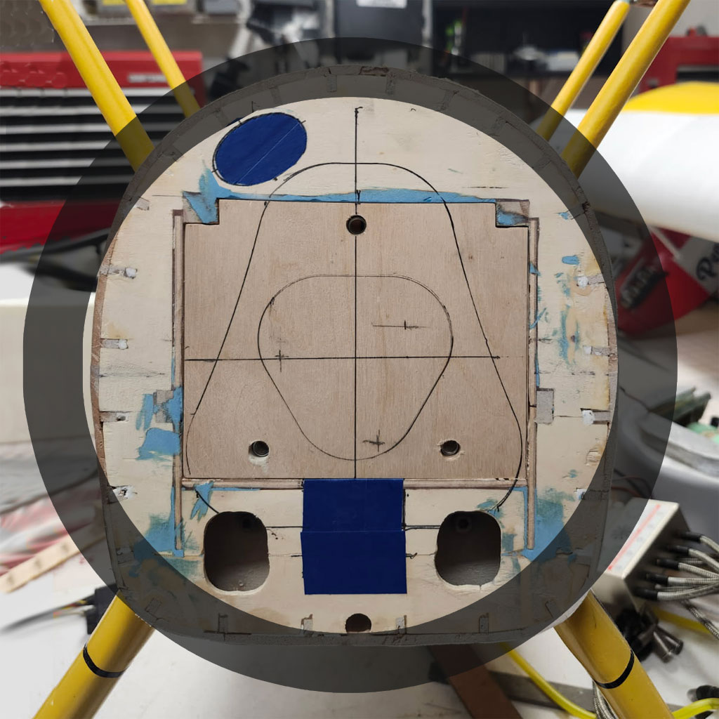
- And we're back to where he initially proposed making clearance
So after he sees this photo, and being a man of few words, he goes, 'Yup!', and that was that. By the way, all this is early in the morning, so we sign off.
Later that day, John shares this next photo. This shows how he's actually made the cut through the inner 1/8-inch plywood box structure and out through former-F3 to route the spark plug leads.
Note; if this photo looks weird, it's because the airframe is upside-down (setting on the cabane struts).
Anyway, if you look closely, you'll also see the socket cap (Allen head) bolts securing the oleo-action landing gear struts (for if you were curious what the other two holes were for and why we didn't want to use them). Oh, and the plan is to fill these holes with a bit of wood later because now they'll be visible whilst before they were hidden by structure.

- Leads routed through the 1/8-in plywood box and former-F3
Unfortunately, there's insufficient width to place the module side-by-side. So it because there is juuuust enough length in the high tension leads for the five on one side to snake straight through whilst the other four make a 180° and loop through, that's the plan. But it's a near thing.
Committing - time for epoxy
Setting back on the landing gear and with the firewall epoxied in place . . . tada!
Yes, John's right, the leads will be ugly but guess what? I don't care because they won't get scummy with oil. That, and I figure folks will be so bedazzled by the gorgeous engine, they'll probably overlook the decision process regarding how to actually get 9-leads through the front of a Ziroli Stearman designed before engines with separate ignition modules existed! This, without compromising the mechanical integrity of the structure!
After all, the engine goes +9-pounds and we can't very well have it falling off due to a rough landing, eh?
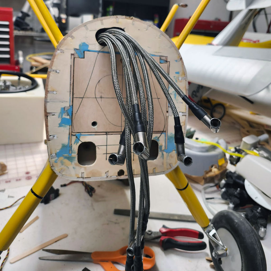
- At last, the firewall epoxied in place
Pinning
What's next? Well, due to his extensive modeling experience, what John has done is to pin the firewall. This reinforces the joint where firewall attaches to the rest of the structure. For this purpose he used short pieces of 3/16-inch solid carbon fiber rod. And FWIW, once upon a time he would have used dowel - but - it's his opinion carbon fiber rod is better.
Anyway, drilling at a 45° (approximately 1/2-in in from the edge on each of the four sides), he placed two short pieces of rod (8 pins total). So in this next photo, the pins are already epoxied in place.
Note; the goal for pinning it to mechanically tie-in the 1/2-in aircraft ply firewall and the 1/8-inch aircraft ply box structure.
These eight pins can 'just' be discerned behind the onion paper, which John placed on former-F3 in this next photo.

- Onion paper outline shows the collector ring dimensions
Finishing former-F3
So what's next is rounding off former-F3 a little bit. Problem is, there's less than a 1/4-inch gap between the collector ring and the former's surface. A bit more wood would look better. We're undecided what to do. Me? I'm not terribly distressed at having a modest radius.
So what will we do? Dunno, but in this next photo, that's a piece of 1/4-in balsa beside the collector ring for scale.

- Exhaust collector clearance is less than 1/4-inch
Center of Gravity, part II
Meanwhile, John's idea is maybe we shorten the exhaust headers a little bit, thus allowing the collector ring to move closer toward the cylinder heads. This would give us more room to round off the former by adding balsa. The other thing he mentions is we don't yet really know (until we hang the engine) what the CG situation is. Like could we maybe we need a touch of nose weight? That means an 1/8-1/4 inch spacer behind the engine mount (possibly) to add space for more balsa.
Moreover, on the same track, if the engine stays where it is, he observes there's about a 3/4-inch straight section after the bend exiting the head. And depending on if we do need nose weight, then he reasons there's no issue with cutting the exhaust stubs a little bit shorter than supplied.
John's point? If the CG needs shifting forward, then he's thinking maybe we kill two birds with one stone because this makes more clearance for some balsa to round off the front end 'and' at the same time, the weight of the collector ring going forward maybe helps with balance.
So because we know we can snake a long Allen ball-end driver past the heads to affix the mounting screws, I reached out to Adrian and he confirms there are no performance reasons against shortening the headers and moving the collector ring forward. But all this is 'really' putting the cart ahead of the horse. First we have to hang the engine and see where we stand.
Hanging the engine
So John called the other morning and said he'd installed the engine. When he said this, I held my breath to hear what came next.

- And here's the UMS 9-115 hanging in all it's glory
Recapping, the concern was installing a 9 pound 3 ounce power plant in place of the <3 pound DLE 35RA would result in the model being nose heavy as Hell. To the point we'd discussed relocating the servos aft beneath the stabs (XA-airplane style). However, John was rather more confident about the whole thing. Like he seemed totally unconcerned things would work out.
So you'll recall his thesis was he'd added a ton of lead to get the model to balance with the DLE, 'and' he was moving the firewall back to former F-3. Still, I'm rather less sanguine about the outcome. After all, we've taken a gorgeous and perfectly flyable model and chopped the nose off it! Yes, removing 9 pounds 9 ounces in the process, but still, theory is one thing, practice is where the rubber hits the road.
So there I am, still I'm holding my breath, and he pauses, maybe not to intentionally drag it out - but - nevertheless, a pregnant pause, and says . . . it came out a bit tail heavy. Some may recall the line George Peppard utters in his role as Hannibal Smith in the television program The A-team, I love it when a plan comes together and this perfectly describes how i received this news of it being tail heavy! Or putting it another way, yippee!
Honestly, tail heavy is really easy to sort when the engine goes north of 9 pounds, agreed? Anyway, as you can see in this next photo, things are a bit tight between collector ring and former-F3 (as we already knew t would be). Securing the engine bolts with an Allen driver was easy enough - but - bringing torque to bear required switching to a Chapman tool with Allen driver. And even then it was a tight fit.

- #3 Chapman tool kits for working tight quarters
Bottom line? Tail heavy means we can shift the whole thing forward, which at the same time means leaving the collector ring alone so we may add some balsa to the front of former-F3 and round it off to a visually pleasing radius.

- Very little gap between former-F3 and collective ring
Prop hub
So because tail heavy is easily sorted, right now the plan is to initially calculate the CG with the known weight of the Ramoser prop. The 2-blade hub, his part number 214-25 goes 82.9 grams. And each blade (to end up at 23.6 inch diameter) is part number 599-25 goes 59.7 gram. They combine for a total of 202.3 grams, and converting to ounces is easy because an ounce is 28.34952, so rounding up, we get 202.3 grams ÷ 28.35 grams/ounce = 7.14 ounces.
Anyway, if you're unfamiliar with the brand, this German guy name of Christian Ramoser makes these wild ground adjustable hubs in various sizes and in varying number of blades. He markets them as Varioprop.
The hubs are offered in sizes ranging from the smallest (A) through the largest (I) and I'm selecting size F, the next to largest (for reasons unknown, he skips some letters). And the best part is, his hubs are offered in 2, 3, 4, and 5 blade variations.
Then to top it off, he offers blades in various diameters and profiles. Point being, you can darn near match any warbird prop your heart desires. I've ordered from him for my Spitfire with 4-blades, a 3-blade for an Fw-190, etc. Plus now, a 2-blade hub is on order for the Stearman!
Oh, and so you know what to expect . . .
Hello John,
It's nice to hear from you again. For your UMS 115/9 and Stearman I would try an adjustable
2-Blade Propeller with a diameter of 23.8”. So I offer this propeller together with a bushing
and spinner cap as follows:
_________________________________________________________________________________________________
1)   214-25   25F 2-Blade-Hub-25F                      - |     -  14.0 Millimeter            76.00
- Gearbox inside  for   synchronous
- adjustment  of   propeller  pitch
- pitch-gauge and pointer pin
- Max. diameter of hub:  ca. 65.0mm
- Thickness of hub    :  ca. 33.0mm
- Weight of hub       :  ca.   97 g
- Range of pitch      :  6” ... 35”
1)   99999    25F Alu-Bushing                          - |     -  Da=14mm, Di=10mm            9.00

1)   SS43-25  25F Scale-Spinnerkappe                   - |     -  D = 43 mm  / M4            39.00
- For mounting this Spinner an internal thread with M4, inside the engine shaft is required.
Please tell if this is not provided.
2)   604-25   25F CFK-Rotorblatt SG                 7100 |  6300  23.8" 60.40 cm             36.00
- paintwork in all black-matt incl. vP-Decals
_________________________________________________________________________________________________
Total Price:                                                                           160.00 EUR
Shipping / Packing / Fright :                                                           34.97 EUR
PayPal-Fees:                                                                            10.43 EUR
_________________________________________________________________________________________________
Amount of Invoice:                                                                     205.40 EUR
. . . and at the time of this writing (€1 EUR = 1.144 USD) this works out to $235.
Next, let's touch on the blades.
Prop blades
Blade-wise, my plan is to begin with 23.8-inch diameter. And my SWAG is to start off at 14" pf pitch and see what happens (SWAG means scientific wild ass guess). And yes, this is a touch oversize compared to the full scale, which sports a 9-foot diameter prop, which would be 21.6-inch diameter. Flight testing will reveal alternatives.
Speaking of which, I am fortunate how, due to previous orders, I have a fair stock of blades with which to experiment. On hand I have Hamilton Standard F-size profiles which will give me various diameters to include 21.6", 22.7", 23.8", and 25.6" . . . saying I have plenty to play with!
Anyway, these Varioprop hubs and blades are as close to real looking as I can readily get. And being able to ground adjust the pitch means matching to load to the engine more closely. And an added plus in my book is if I break one, I just install another blade instead of throwing the whole thing away.
In summary, these Varioprop units may look a bit pricey upon entry to the game, but ongoing expenses are rather more attractive in my opinion because even if I destroy both blades, I'm still only looking at $40 plus shipping. This is comparable to wood props, and about half the going rate for carbon fiber props. moreover, since I tend to buy several sets at once, the unit cost runs less than $50 for a prop.
Considering a) it looks more realistic, b) offers infinitely adjustable pitch, c) I can replace single-blades, then this makes it both superior to either alternative, and something of a bargain in my view - but - you do you!
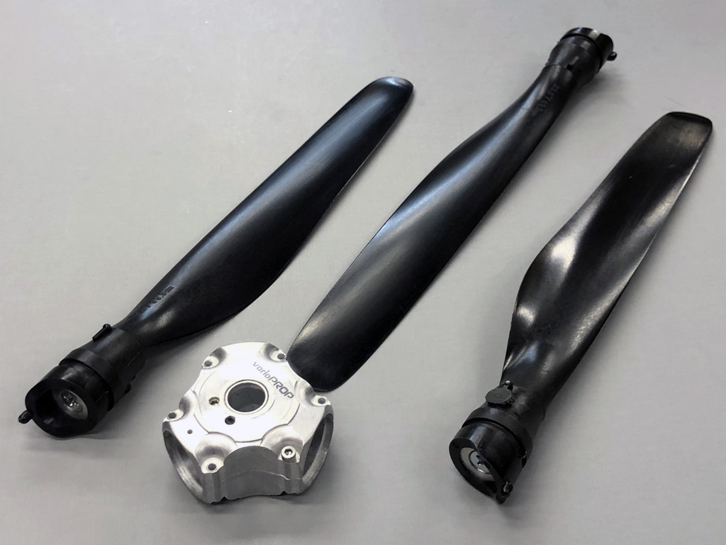
- 3-blade size-F hub with Hamilton Standard profile blades for 23.6 inch diameter
So here's where we are, now. The engine is hung and we're needing to move forward about 1/2-in to bring the balance point to the CG specified on the plans.
Our next move is to remove the engine, and dress up the forward part with balsa in order to round the shape of the former a bit to make things look better. Also, fuel proof the tank compartment, add a bit of silver paint, run fuel lines, throttle pushrod, etc.
So we're getting closer!

- LaBelle Stearman with UMS 9-115 mounted
Fuel system
What remains are some housekeeping tasks. Speaking of the fuel system - tank, lines, and pump. Also avionics - servos, battery pack, kill switch, radio switch, etc.
We'll begin with the tank, lines, pump, etc.
Fuel tank
What's fitted is a 20oz Du-Bro, there's room for a 24oz, but in speaking with folks, this is a thrifty engine, and I'm wondering if a 16oz will work. Typical of 4-stroke engines, consumption is about half that of a 2-stroke of equivalent displacement. Added to which, when the 2-stroke is screaming away at 7000RPM, this one is at more like 4500RPMs. I'm seeking more data before committing.
Another consideration is how I'll be flying the model. Unlike a Mustang or Bearcat, in the real world, I doubt within the Stearman WOT (wide open throttle) extends beyond maybe15-seconds for take off and initial climb out, and maybe 5-8 seconds to initiate a loop. Suspect the rest of the time, part throttle ops are the norm (think cruising around at <2500RPM). Anyway, like I said, it's my hope to replace the 20oz with a 16oz tank - but - for now, we're leaving the 20oz in place.
Meanwhile, this will be a 3-line system, drain, return, and vent. The plan is for the vent line to just dump overboard at the bottom. That, plus an ordinary fuel dot for fill. However, there will be two Ts in the system. In a bit we'll get to Richard Dochterman's diagram detailing this. And yes, at flying fields where it's an issue, this setup makes it easy to collect fuel vented overboard into a catch container whilst filling.
Note; things have worked out such that the center of the tank aligns with the CG - perfectly - and thus, as fuel burns off, the CG won't change. Pretty sweet!
Fuel lines
We're turning to translucent yellow Tygon tubing. Once everything is proved, I may switch to neoprene (the black stuff). This, because in my experience, it just lasts longer. Basically, the Tygon goes to jelly over time, which I find to be a monumental pain in the ass. But that's measured in years, so it's Tygon for now.
Fuel pump
As I learned within the rabbit hole thread, these UMS radials are unique amongst gassers (in my experience) in needing a fuel pump to run. This, because the Walbro carburetor doesn't receive sufficient vacuum-signal to operate. Question is, which pump to use? There are several on the market, all somewhat expensive. And unsurprisingly, all have their proponents and detractors - think Ford vs Chevy!
Anyway, a very helpful fellow within the thread (Robert Dochterman) has a UMS 5-100 mounted in a Black Horse Model Gilmore air racer. If it doesn't ring a bell, it's an air racer of the 1930s. The aircraft was famous for the pilot, Roscoe Turner, and his pet lion, Gilmore. Named for the Gilmore Oil Company who put him up to it with the usual incentives (money), the whole thing, lion included, was a publicity stunt. This, to attract attention to the brand. And no surprise in air racing crazy America of the day, it worked! Everybody talked about Gilmore, and today, closing on 100 years later . . . here we still are!

Note; learn more with this Wikipedia article if you're curious!
By the way, I'm offering up this 2:10 long YouTube video of it in flight (of Robert's Gilmore racer) because it demonstrates the model's sparkling performance with his UMS 5-100 engine. I share it because I expect the 9-115 to perform similarly. This, because I expect the 15% added displacement will be offset by the 80% increase in ring drag. in fact, I wouldn't be surprised if it may under perform the 5-100 slightly!
Anyway, and circling back to what this section is actually about, it was on Robert's recommendation that I purchased a TCS Micropump M400k-v for my engine.
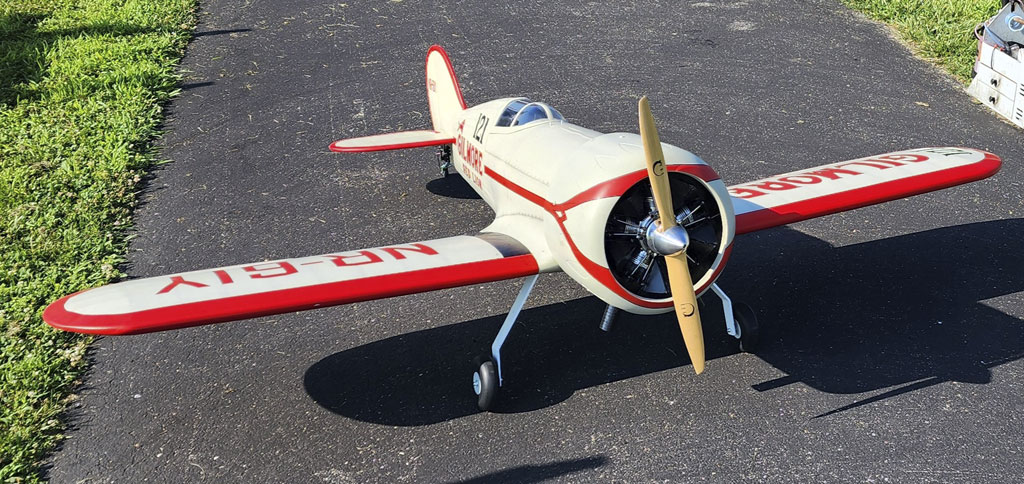
- Gorgeous UMS 5-100 powers this Black Horse Model's Glmore air racer
On Selecting the pump
Since I'm not about re-inventing the wheel, when Robert Dochterman shared details of his pump installation (and video proof of everything working), then I followed his advice and ordered one. And seemingly somewhat rare these days, this very nicely made high quality English product wasn't of east Asian origin! No, I'm not being political, just making an observation I don't see a lot of products from the United Kingdom on our shores these day. Anyway, in due course, it arrived.
So here's the thing; despite having downloaded a document with product description and dimensions, I was nevertheless taken aback at how compact it is. This pump is tiny! Anyway, it's supplied with 5 bare leads - no connector. This, of course, is no big deal because my plan is to wire it to a servo extension equipped with the standard DuPont connector we use in our sport for receivers, servos, batteries, and switches. Easy peasy!
Note; since there's no USA representation, I inquired because I thought these lovely pumps would make nice addition to our product line. Unfortunately, they had no interest - but - this didn't hurt my feelings, nor stop me spending some money with them!
Here's a link to the pump; TCS Micropump M400k-v
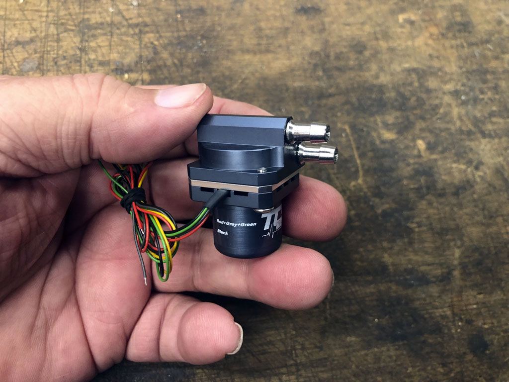
- TCS Micropump model M400k-v
Plumbing the pump
So there are a couple things to sort with this thing. For example, it comes wired with 5-leads. We're only using two of them. Also, it's been advise to plumb the pump to recirculate excess fuel back to the tank. As it happens, this is how the fuel system in my Bonanza functions, as well as modern day fuel injected automobile engines so it's not a totally foreign concept. Basically, the pump run continuously and then a T-fitting allows returning excess fuel to the tank. Necessary because otherwise, the carburetor fuel delivery circuits are unhappy.
Let's look at this, first. Below is the sketch Robert shared with me. In it he calls for a couple T's in the fuel line. Both are ahead of the pump outlet and carburetor inlet. This, allow for return fuel and for filling and emptying the fuel tank.
And a critical component is the manual valve to regulate the head at the carburetor inlet by restricting the amount of fuel returning to the tank. He used a Flow-Rite PV-2W pinch valve, which he found at McMaster and which, I found via Amazon. Same thing, use your supplier of choice.
Me? I'm thinking a wheel collar will also do the trick!
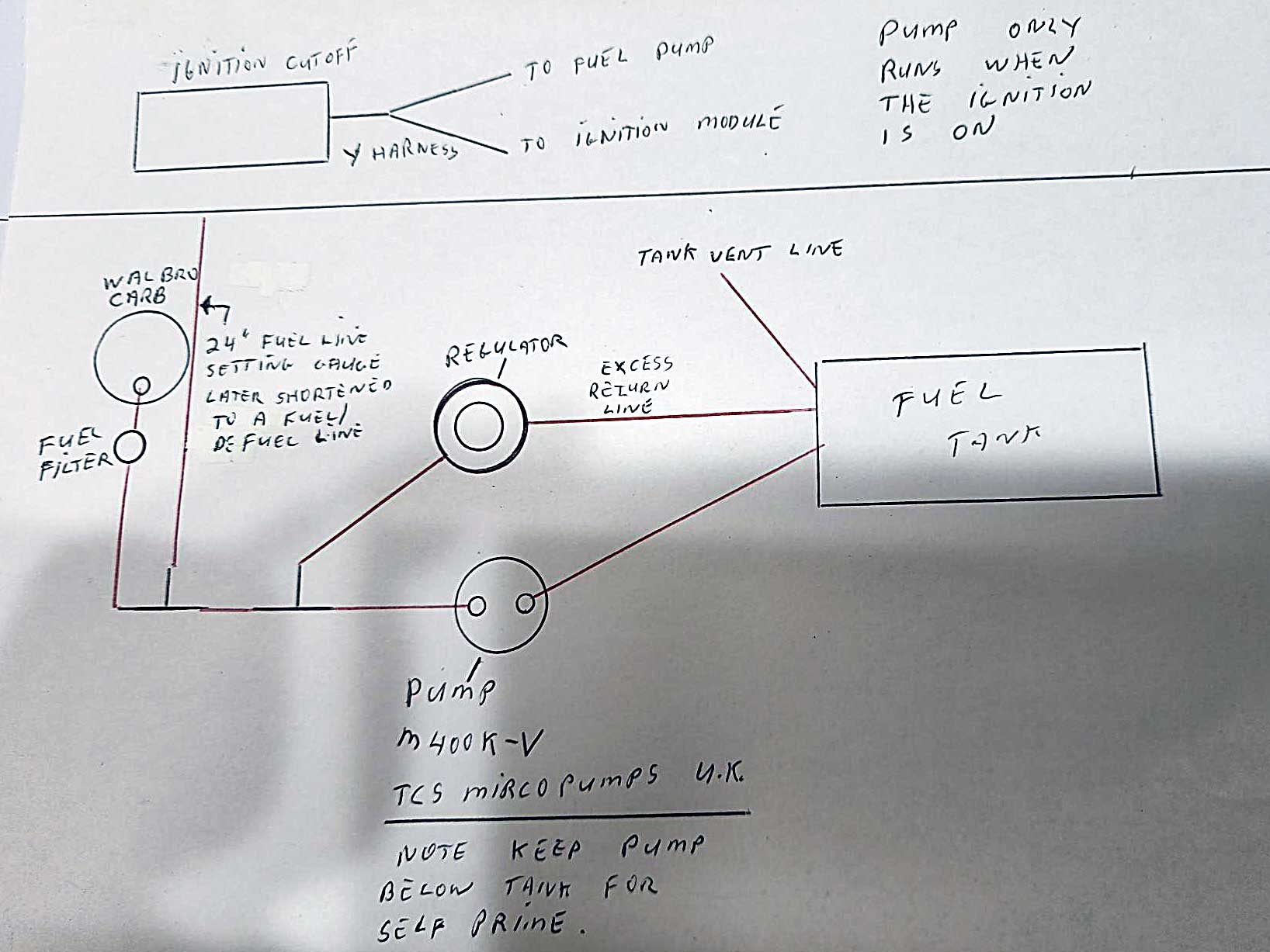
- Robert Dochterman's fuel flow diagram
Wiring the pump
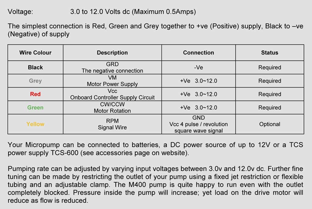
So up next is wiring the pump, and it couldn't be more simple despite coming with 5 leads.
As supplied, there are red, black, green, gray, and yellow leads. The individual leads are thin, like maybe 32AWG. This, because the pump doesn't draw much current. As for the input voltage, it may range is from 3-12VDC. This is the pertinent info off the spec sheet.
Soldering it up
What they recommend wiring-wise is connecting red with green and gray to the (+) lead, and black to the (-) lead. Yellow isn't used.
So I removed the yellow lead from a ProModeler 12-inch extension, and soldered red/gray/green-to-red and black-to-brown like they said. Bit of heat shrink tubing to make a neat job of it and Bob's your uncle!
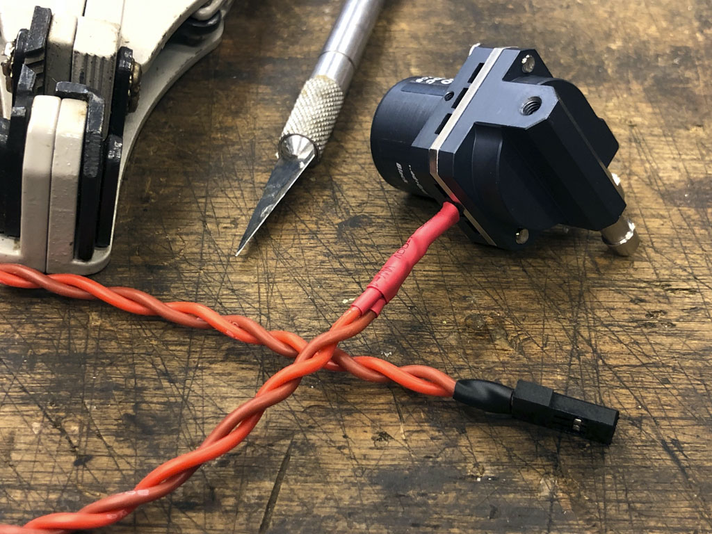
- A bit of heat shrink at both ends makes for a clean setup
Connecting the pump
When it comes to hookup, the plan is simplicity itself. Basically, plug the pump into a Y-harness along with the opto-kill switch. Then, when I engage a switch on my transmitter to power the ignition, the pump comes on, also. Sure I could use two separate switches but why complicate life? Especially since current draw for both combined will be minimal, e.g. unlikely to exceed the 3.5A continuous current rating of the Y-harness!
Anyway, we own the mold to produce this rather nice 3-inch long Y-harness and it's what I'll use for the job.

- Custom molded ProModeler Y-harness uses 20AWG wire
Avionics
Since we're in the avionics business, forgive me if I now yap-yap a bit about our wares. After our focus on the engine swap of this Nick Ziroli 1/5th scale Stearman, I'm going to take advantage of your good nature and undivided attention (if you don't hit the PageDown key). And no, I won't keep bangin' on for very long, I promise!
We're going to briefly touch on switches, batteries, servos, and arms . . . the avionics of your model. This, to help guide you on your build.
So far we've pretty much proven this model is going to weigh in at about the same whether the engine is a DLE 35RA, Zenoah G-62, or this UMS 9-cylinder radial. Why? Simple, because they come out tail heavy and by the time you ballast the model with lead to get it into the proper CG range, it doesn't much matter what engine you started with.
And if you think about it, this means they all weigh about the same and due to how they're flown, they all perform similarly, And by extension, this means they place similar requirements on the avionics. Let's delve in.
Mechanical switch
You're going to need three mechanical switches. One for the pump but even if your engine doesn't use a pump, you're still going to pair a mechanical switch to meet the proviso of being able to kill the engine external to the model without using the radio. For this (using the radio) you also use an opto-kill switch before the manual kill switch (so both go between ignition battery and ignition-module).
Since I am using a pump, I'm going to use a Y-harness for both the switch and the pump. This, so even though I disengage the opto-kill using a switch on the transmitter, I can still de-activate the battery to the ignition to allow the pump to function. I need this to be able to prime the engine without it starting. Point being, the engine won't actually receive juice from the battery powering the ignition while the pump will operate. Thus, just as with an engine without pumps, the purpose of the manual switch is to give me a way to kill the engine without the transmitter. And with a pump-equipped engine, it allows me to have the pump running whilst I prime the engine. Fortunate because I'm rather attached to my fingers! Think of it as an inexpensive safety measure.
Toward that aim, we offer this shielded 5A slide switch and it will do the job nicely.
Note; you're actually going to need three of these, but we'll get to the other two in a moment.
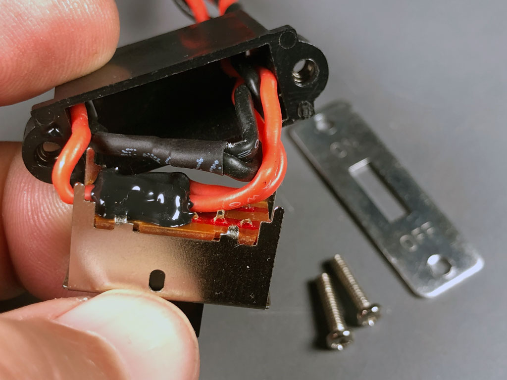
- ProModeler slide switch features shielded 5A Nobel brand and potting compound
Above is what's hidden on our switch. The bent metal is the shield against stray RFI (typically ignition noise). Hobby grade switches lack the shielding. By the way, we're using a genuine Japanese Nobel brand switch instead of a cheaper knockoff.
Note; eyeball the black stuff on the solder joints, which is called potting compound. This is important.
The idea behind using potting compound being to better protect the switch against failure due to vibration. Less obvious is the wire for the harness. We spec high strand count 20AWG copper, and because I spec the insulation, also, you get that soft supple silicone instead of PVC. This, because it flexes easily and resist abrasion better. Basically, you're getting the best switch I can get made up. Moreover, we have other switches if you prefer a different style.
That said, and believe it or not, I hate switches!
Honestly, I feel the best are the ones in a drawer in the workshop. Works if you can conveniently use an extension to make/break battery power. So if you can suss out a way to avoid using a switch, then my advice is leave the switch off the model. Unfortunately, sometimes, switches are unavoidable. With this Ziroli PT-17, it's one of those times because we don't have ready access to the inside of the aicraft like we have with modern models like an Extra 300 where the forward part of the fuselage opens up for access with just a latch.
Why 3 switches instead of 2?
Most modelers use two switches. One for the ignition kill, and another for the radio. However, I recommend three, where one is for the ignition, and there are two in parallel for the radio. Why?
Simple, to safeguard against switch failure. How? Through mathematics. Basically, the odds of both radio switches in parallel failing on the same flight are astronomical. So why not two switches for the ignition?
Simple, also. If the one switch craps out - unlike with the radio switch which instantly turns you into a spectator as your model makes a smokin' hole in the ground - it's likely the worst that happens is a dead stick landing.
Note; we produce these switches. They're the same ones I use for my own models. However, because switches - no matter how good - are prone to failure, then I take advantage of mathematics to stack the deck. How? Simple, I use two switches in parallel from one battery to power the receiver.
This brings us around to discussing flight packs since using two switches requires a battery pack with dual leads.
Battery packs
Just as I spec switch components, I also spec our packs. While I could offer cheaper battery packs if I specced cells packed in plastic bags, instead I opt for cells built within cylindrical metal shell. Why? Simple, because they're safer than cells packaged in plastic bags (like LiPo and Life). As a practical matter metal-shell cells are just more robust against the everyday bumps and knocks life brings with it. This is important as it helps guard against fire risk.
I also have them built with 3 discharge connectors. And while we offer LiIon-chemistry, I save those for XA-type models where I want higher voltage to get the most out of my servos. For sport and scale, as as a general rule, I prefer LiFePO4-chemistry. Why?
Lower potential due to the more 'chill' chemistry. This just means LiFePO4 is less prone to catching fire than packs with higher voltage. Fire? Yes, so heads up a 6.6V pack is less dangerous than a 7.4V pack. And both - because they're in metal shells, are significantly safer than packs built in plastic bags.
Note; the chemistry of LiIon and LiPo are similar, the changes principally are those to allow them to be rolled up versus being built flat. Similarly, LiFe and LiFePO4 are similar, the latter again allowing them to be rolled into a shell. And no, LiFePO4 and LiFe are NOT the same thing despite being able to use the same settings on chargers.
Point being, if you prefer using LiFe because it saves money, as long as you add a 2nd discharge connector to run two switches, it doesn't matter to me, and the servos don't care, so do what's best for you.
Anyway, in this next photo, eyeball how there are two are DuPont type connectors on 20AWG leads plus an XT30 on 16AWG leads. By the way, hobbyists may refer to the DuPont connectors by a brand name, often JR. We don't fight the nomenclature war because we're talking about the same thing.
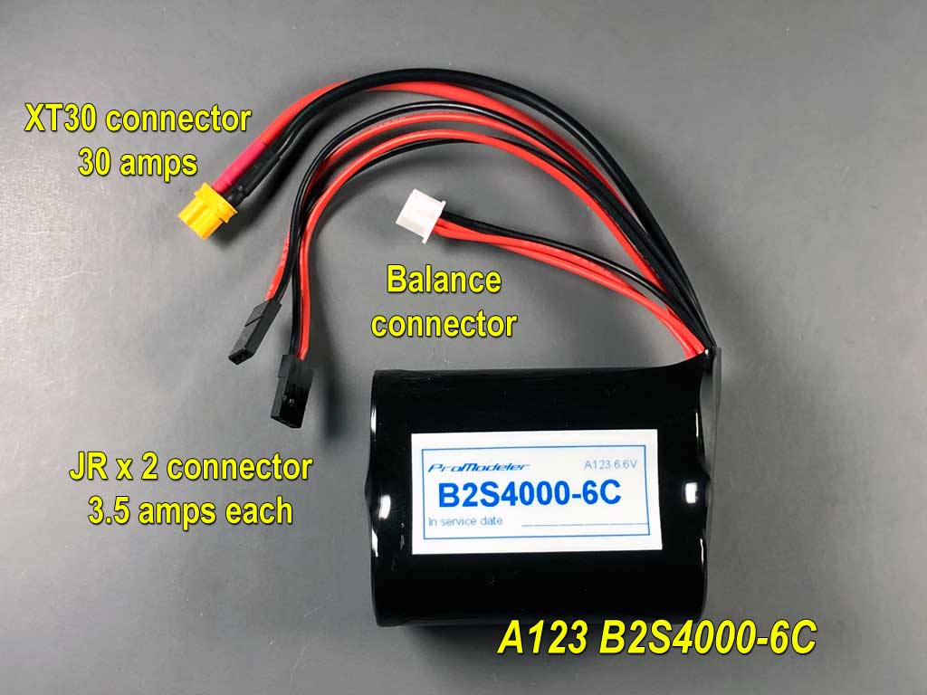
- 4000mAh pack comprised of LiFePO4 metal encased cells
Dupont Connectors
Anyway, equipping batteries with two DuPont connectors makes using two switches easy. In fact, building packs with two leads was ProModeler's first product +40 years ago!
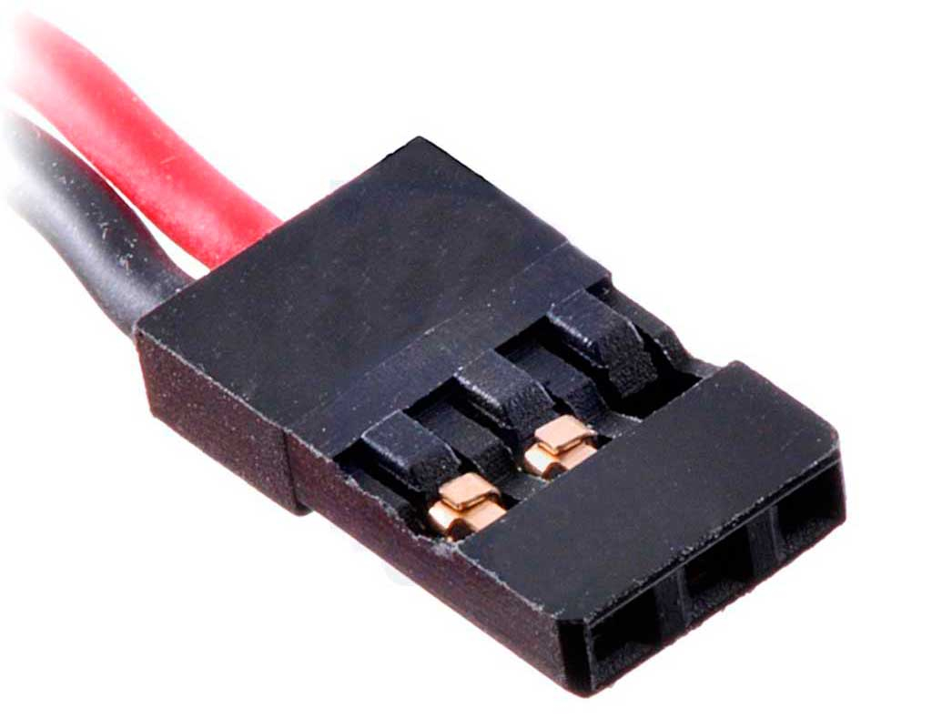
- The ubiquitous DuPont connector
Way it works is you connect one battery lead to a switch and then plug the switch into the receiver where it usually plugs in (often a port marked BAT). The other battery lead goes to the second switch and connects at any available port on the receiver. Any port?
Yes, and this works because receivers use what's referred to as a bus structure for DC-in. Means you can actually connect the battery anywhere versus the port marked BAT. Best part of doing this? There is another advantage of dual leads (beside reducing the odds of crashing due to switch failure).
Reduced current flow
A further practical benefit of using two leads is current flow through each connector to the receiver is automatically halved. So if the entire model draws 5A, then with two connections from the battery, each connection sees 1/2 of this value, or 2.5A.
Less current flow means less heat. This translate into a longer working life. Both are good things.
However, but putting odds to work for you is the 'real' reason I like using two switches. Cutting current flow in half is nice but mostly a bonus in my eyes except at edge cases beyond the scope of this white paper. Anyway, we'll show the switches I ended up using later.
XT30 connector
Then there's also an XT30 connector (with heavier 16AWG leads). I mostly use this one to charge my packs despite the fact the switches have a red-DuPont connector for this purpose. The reason is these XT30 are a more robust connector and thus, better suited to repeated handling, in my opinion.
Balance connector
Finally, there's the balance connector. This one allows the charger to know the state of voltage on a cell-by-cell basis. This is how the charger 'knows' to bleed current from the pack whilst charging until the last cell to peak reaches the appropriate level and shuts off the cycle.
Note; you never want to charge lithium chemistry cells with a dumb charger, meaning a charger not equipped with a balance connector. Consider yourself warned and don't say you've never been told.
Servos
As you would expect, I'll pull the Hitec servos John LaBelle installed in favor of ProModeler servos. Maybe due to the overall expense of this project you suspect I'll select some of our pricey brushless alloy servos like our DS505BLHV in the photo below. But you'd be mistaken. Why?

- ProModeler DS505BLHV is a top seller
The reason I wouldn't select top-of-the-range brushless servos like our DS505BLHV for this Stearman sporting a $3000 engine is because 500oz-in is severe overkill. That, and 0.10sec/60° is waaay faster than necessary. Also, because of the price.
Look, if my model needs this much performance, then I have no choice - but - since I don't feel the need for this level of performance for a Stearman, then my view is; why pay for something I can't feel in flight?
In short, because a DS505BLHV is both stronger and faster than I need, I can instead save money and spec a less costly servo because quality with ProModeler is not dictated by price.
Note; we spec the same Nobel brand million-cycle potentiometer in all our standard class servos so centering performance is excellent regardless of price.
Who benefits from a DS505BLHV?
That said, far be it from me to stop someone who has an actual need for brushless 500oz-in servos in a 1/5th scale warbird form buying them. And you know who you are (e.g. guys who fly a Mustang like they stole it). Ditto, folks engaged in organized warbird air racing. You guys have a different servo requirement than the average club pilot like me. Ditto those of you who go overboard in the engine department and stuff something wicked under the hood - think DA-85.
Who else benefits from a DS505BLHV? Warbirds going 35 pounds instead of 25 pounds definitely qualify. But mostly it's guys flying 90-inch wingspan XA-type model, or in a 103-inch wingspan IMAC-type. Major point being, I'm going to keep the extra coin in my pocket and opt for something a bit less pricey. Surprised I'm giving money the same consideration you give when forking over money equipping a model with servos?
Don't be because, believe it or not, I have to pay for servos just like you and everybody else. Sure, I fill my pockets at the warehouse, but before I leave, I must sign a chit. A chit is basically an IOU. It's how I get billed for my servos. So while I own the company, servos are inventory. And inventory control is part and parcel with operating a warehouse. So I buy them like everybody else to keep the books in order. Also means I don't piss away money installing more servo than called for. Neither should you!
Anyway, and continuing briefly on the subject of the DS505BLHV, allow me a brief birdwalk. Meet Cam DeVries.

Repair or toss?
So an interesting story developed around young Cam after his Dad took the above photo. He wrote relating about having an accident with his model. Seems he'd torn the crap out of a couple of servos and wondered if he should toss them and buy new. I said. Let us take a look before to fork over so much dough, maybe we'll surprise you. So I gave him an RMA that he could return them for service
Note; if you think the shafts look bad, you should have seen the insides because these servos were basically trashed!
Anyway, when the tech received them, he was so astonished at the damage we ended up photographing the repair process. Point being, if you've ever wondered what goes into a set of our servos, this is a good article to review - On rebuilding damaged DS505s as these are typical photos.
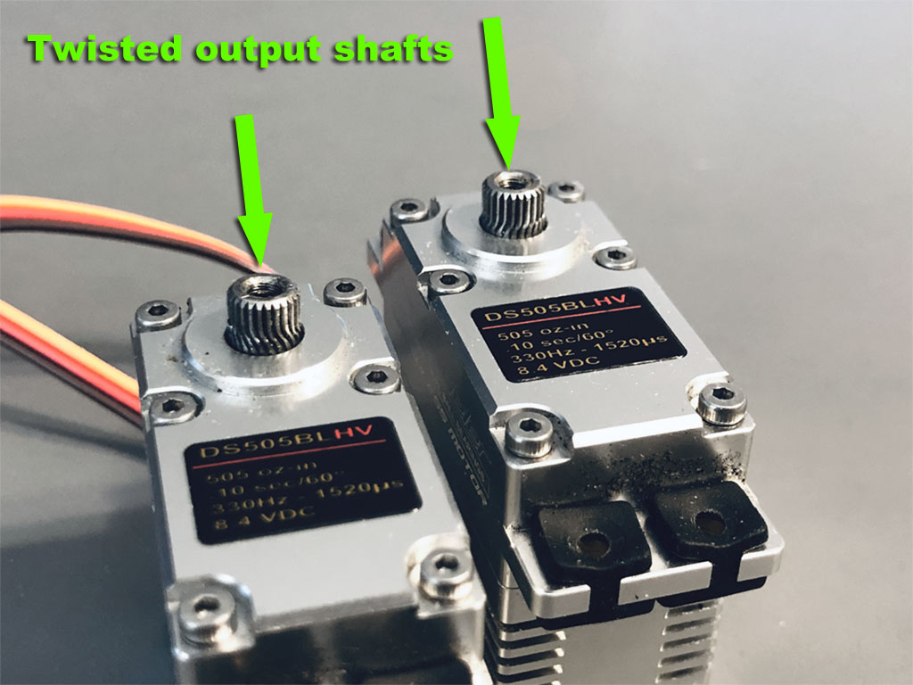
- An impact was so severe stainless steel output shafts twisted
Servos
Anyway, back to the Stearman and the question is, what am I going to use for servos? Short answer; I try to select servos based on expected flight loads. The other consideration is the voltage. So exactly as I would advise a customer making an inquiry of what servos to use for their WWII model, I need some information about powering the avinics. That said, I have loads of experience with 5th scale warirds, which is DS180DLHV work, but I like to make more than that much torque available so long story shortened, my servo of choice for this Stearman is the DS360DLHV on flioght controsl and DS90DLHV for throttle. Why a popularly priced DL-series servos versus an all-singing, all-dancing brushless servo for a model sporting a $3000 engine on the nose?
Simple, with proModeler there's no relationship between price and reliability. And for how I plan to power the avionics, I'll sleep fine with making servos rated at 360oz-in on 8.4VDC what i'll rely on.

- Installed three abreast to the stabs, throttle below
So because I can see the wheels turning in your head, let me explain why. First, like everybody else, I've seen a 1/5th scale Stearman model fly with the Hitec HS5645MG with which it's already equipped, or ~180oz-in. Some of you may be wondering why we don't substitute our DS180DLHV as they cross over nicely? Not a bad question, but before I explain my thinking, review how these two two servos match up in the real world.
As to why do I feel the need for 360oz-in servos? This relates to input voltage. Before I can I decide on which servos I want to use, the first thing I consider is the power source for the avionics, e.g. the voltage. This matters because voltage determines what we'll get out of the servo. Basically, the higher the voltage the better it performs (until it goes over 8.4V whereby the servo then goes poof and releases the magic smoke).
Let me explain about batteries before getting to torque ratings.
input voltage determines output torque
So we publish specs for every servo. And when a fellow calls to inquire about servos, the first question out of my mouth is; How do you plan to power the avionics? Me? My favorite packs are comprised if LFP cells. LFP is short for Lithium Iron Phosphate, or LiFePO4. Why?
Very simple, it's because they're easy to live with. Easier because I'm lazy. Basically, I dislike having to take a pack I didn't fully discharge down to storage voltage after I get the model back to the shop. Reason I love LFP cells is partly due to their ability to resist being damaged if I ignore them, instead of running a storage mode on them.. Honestly, this alone is the reason why I'd opt for a bit more powerful servo to make up for reduced input voltage. But I also like them because being lower voltage than LiPo, they're safer, e.g. less fire risk.
So let me explain . . . voltage determines performance. But of course, there are plusses and minuses to everything, so let's review;
Upsides
- You can charge and ignore LFP for months if you don't use them immediately (you don't have to put them at storage chargeas with LiPo and LiIon).
- Also, due to lower voltage potential, they don't pose as great a fire risk in your shop/house.
- Plus, while similar chemistry-wise to ordinary LiFe packs, being encased in metal shells instead of plastic bags means they're significantly more robust, e.g. better withstand the everyday bumps and knocks packs encounter in the real world.
Downsides
- They're a bit more expensive - but - everything is relative and when you're ponying up as much as you are for avionics and the rest of a model, then the added $20-30 is a drop in the bucket.
- They're lower voltage than a LiPo. Why does this matter?
Simply this; servos are rated on their input voltage. The higher the voltage the better they perform. This is true for all servos, all brands (us, Futaba, MKS, SAVOX, Futaba, Hitec, everybody). So just like everybody else, we put lipstick on the pig, e.g. brag about them at the highest voltage.
Dishonest? Nope, because we disclose within the specs what to expect on other types of packs. Basically, every servo we offer includes a spec chart similar to this one.
Note; what you want to focus on are the five voltage-columns (basically selecting the battery chemistry you're going to use).
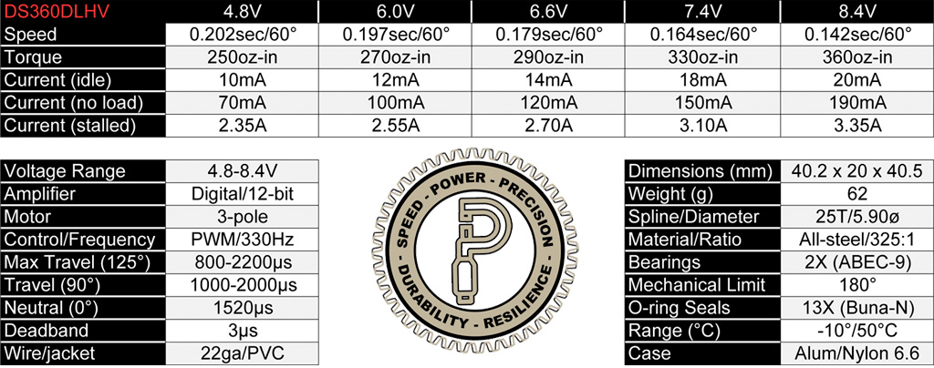
In a nutshell
- 5V is for 4-cell NiCd or NiMH
- 6V is 5-cell packs of the same
- 6.6 is 2S LFP or LiFe
- 7.4 is 2S LiIon
- 8.4V is 2S LiPo (or BEC regulator you set)
. . . and for what it's worth, I don't EVER rely on a BEC.
What's in a name?
Or paraphrasing Juliette's, That which we call a rose by any other name would smell as sweet, a battery eliminator circuits (BEC) is just a voltage regulator. And straight up, I don't trust any hobby grade regulator. Basically, I'll take trusty analog (batteries) versus digital (BEC) any day of the week. Why?
Principally due to performance (and for many of the same reason pro audio opts for analog amps over digital amplifiers, the juice is just cleaner). But also because of the odds. Odds?
Yes, because when you look at the BOM (bill of materials) for a BEC, basically you're inserting 30-50 additional components into the failure chain. Put another way, there's just more to go wrong! And as we all know, KISS rules everything! KISS of course being the acronym for keep it simple silly! Put another way, less is better.
But add to this, BECs can burn up.
What's the argument in favor of BECs?
The basic claim BEC-sellers are making is you get more steady voltage during the flight. Me? I call bullshit because pack discharge curves are so flat there's not a pilot on earth can feel the difference in 15-minute flight. Seriously, I don't care who they are or what they claim, it's bullshit because the discharge curve virtually doesn't drop until the pack's near the end of useful charge. Fact.
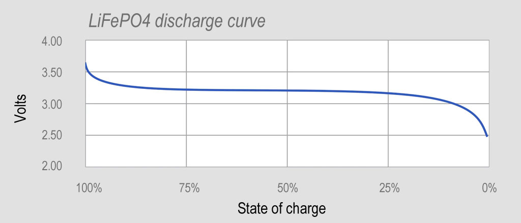
- Discharge curve chart for LFP battery packs
Mathematics
But let's circle back around to odds. Odds are what built Las Vegas. So because more components equals more shit to go wrong, even if digital juice were as clean as analog, I'd still say pass just because of the additional components to make the device. A100% of these additional components come in addition to the battery pack because a BEC is 'still' relying on batteries to power the magic.
Anyway, as an engineer, I make it a practice to never argue against odds. This makes my advice of relying on a flight pack versus a BEC circuit something of a no brainer because the marketing types can whisper their sweet nothings in my ear until the cows come home, I know better.
2-pack systems
So in recent year it's become the style to rely on two battery pack systems. Devices like 'battery backers' and 'power safe' have become all the rage. As a vendor I should be in favor since the opportunity becomes sell 2-packs vs 1-pack. However, as an engineer, I'm not enthused about two battery packs so my best advice is . . . be careful what you wish for. These are my thoughts.
- With two batteries, you have twice as many to purchase. Also, twice as many to charge, discharge, e.g. maintain.
- Some RF vendors promoting the use of two packs never say why they favor two packs - but - either their RF is famous for brownouts, so dual packs may make this less of an issue, or b) their receivers are stupid expensive. Point being, i can't help but wonder what role is at play in the dual pack recommendation. Then again, I'm recognized for being less than trusting about marketing-types.
- Meanwhile, how do you know the magic is actually working? Like how do you confirm the circuitry that shifts from one battery to the other is actually functioning as designed? For example, before my fat ass takes the active runway with my Bonanza, when I do a run-up, I also switch from one magneto to the other. Basically, 'I' confirm both are working before putting my life at risk. Granted, our toys aren't usualy a risk to life, but there can be a lot of money on the line. But I'm stuck with this question, how do you confirm whatever makes one of these things work, is actually working? Serious question! is there a light that indicated proper function? Or some warning when it's not working as designed? Me? I think the Russians have it right, trust but verify! Question is, how? Anyway, I observe nobody selling these things even mentions this subject. Why is this?
Bottom line? I prefer a single battery pack. Why?
- Well, in my experience, batteries don't just go bad in flight. I've got +50 years under my belt and have NEVER seen a battery just quit. Every single time, the postmortem has reveled someone flew below critical voltage, or forgot to charge the pack - or put another way - the battery quit due to human error
- Alternatively, an one/off switch failed resulting in a loss of juice to the receiver.
- Or the pilot flies an RF system known for brownouts and crashed with all the symptoms of a failed battery before the receiver came back to life after going into low-voltage reset.
. . . and none of this being due to an actual failed battery.
Saying for ions to just decide to stop flowing from cathode to anode out of the blue? Pull the other one! Honestly, that would be like gravity deciding to just stop working one day. Ain't happening!
Note; key to the above is this; the pack is charged - nor - discharged below critical voltage.
So it's my belief guys who feel they need to depend on a 2nd battery pack to take over for a depleted 1st pack never actually know whether it's switched over. Maybe they simply deplete the juice in the second pack, too. Remember, there's nothing telling you the system has worked as advertised, e.g. switched over from one pack to the other.
Also, those who state the system switches over because the voltage of one pack got low are apt to have not actually read the manual for how these things actually function. Thus, they're exposed to being caught with their pants down because of - once again - human error (like they forgot to charge one pack, which means they likely also forgot to charge the other pack). So it's my view these things are all band-aids on the real issue.
Anyway, long story shortened . . . I 'never' start an engine before first checking the flight pack voltage. Never! My advice is get into the habit. Especially as a simple voltmeter will tell you the state of charge.
Next, let's see what role chemistry plays in servo selection.
Why voltage matters
So now let's close the circle. To get 360oz-in out of a DS360DLHV you have to operate them off a LiPo or digital source like a BEC circuit - but - if you opt for LFP, then you're only going to get 290oz-in out of a DS360. While this is still severe overkill compared to a Hitec HS-5645MG, I learned in machine theory to never operate a machine at 100% output. Put another way, better to have 50% in reserve.
So 290oz-in ÷ 2 = 145oz-in, which is in the ballpark for the output of an HS-5645MG on rated voltage. And 'this' is why for this Stearman model, 'I' am selecting our DS360DLHV servos instead of a DS180DLHV, which more closely matches up to a Hitec 645 series.
Incidentally, for the curious, we did a side-by-side teardown of a Hitec D645MW versus the ProModeler DS180DLHV - this link opens in a new tab.
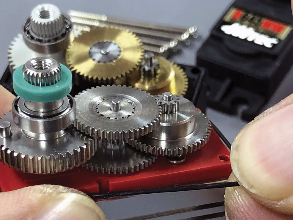
- Close up of the stainless gear train and seals of a DL-series servo
Note; since this servo and our DS360DLHV are built pretty much the same, it's worth your time to see how the servos match up as we compare and contrast what you find inside. That which other manufacturers never show you, the guts!
The servo of choice
Without question, what I am going to use are a set of ProModeler DS360DHV (plus a DS90DLHV for throttle). And I'll be in good company with others flying similarly sized and powered models.

Back to the model
So with the firewall glued in, and using a 1/2" spacer between the supplied standoffs and the alloy mounting plate to to bring the CG to where we want it, next up is a cosmetic detail. The nose ring, which smooths the transition to the firewall/former-F3. All it takes is a bit of 1/2" balsa plus some quality time with sandpaper and presto!
Nose ring
making a nose ring sounds easy - and in fact is easy. The trick is doing it well. So eyeball some of the details.
For example, look how nicely it's clearanced for the spark plug leads where they exit former-F3. Also, note how there's a drain hole in the center (of the bottom edge). This, to account for fuel accumulation due to the carburetor spitting at part throttle.
Details count!
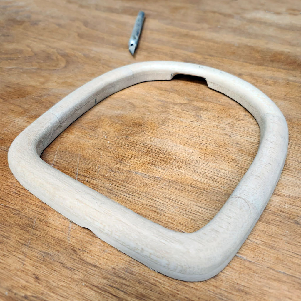
- 1/2-in balsa stock make up the nose ring
So here is the nose ring installed after being covered in 3/4 ounce fiberglass cloth and Z-poxy finishing resin.
Lacks finish sanding and paint. Plan is to use silver. Ep next is hanging the engine again to check for clearance and balance.

- Using 1/2-inch balsa a cowl-ring is fabricated
Recapping, the battle has been locating the engine and balancing the model without any added lead weight. That has been the mission.
So now it's time for a trial fit of the engine but this time with the .500" thick alloy spacers that brings the CG of the model into the ball park. This distance determined how think the nose ring would be. Had the CG been right with 3/8-inch of space, then the nose ring would be 3/8-inch thick instead of 1/2-inch thick.
Test fitting the engine
Anyway, and by pretty much any measure it's looking pretty good, isn't it?
At this stage, verification of throttle linkage to carburetor arm is confirmed. And the fuel line routing is also confirmed. Recall we need to use 3-lines, one to fill, one to vent, one from which the engine draws fuel.
This brings us to the fuel pump. Basically invisible in this shot, let's briefly circle back to fitting it to the model because this engine calls for one.
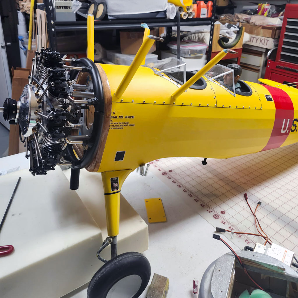
- UMS 9-115 engine has been hung with .500" alloy spacers
Fuel pump
The purpose of this photo is to show how the fuel pump gets installed.
Basically, make a bore in the firewall of about the diameter of a quarter and then the pump motor slides in leaving just the pump body exposed. Thinking a dab of silicone rubber keeps it in place - yes, we're going to glue it in place!
Note; nipples facing up turned out most convenient. The benefit of this placement below the tank means priming the unit is dead buts easy. Moreover, it shouldn't loose prime. Important because the vendor says to not operate the pump dry.
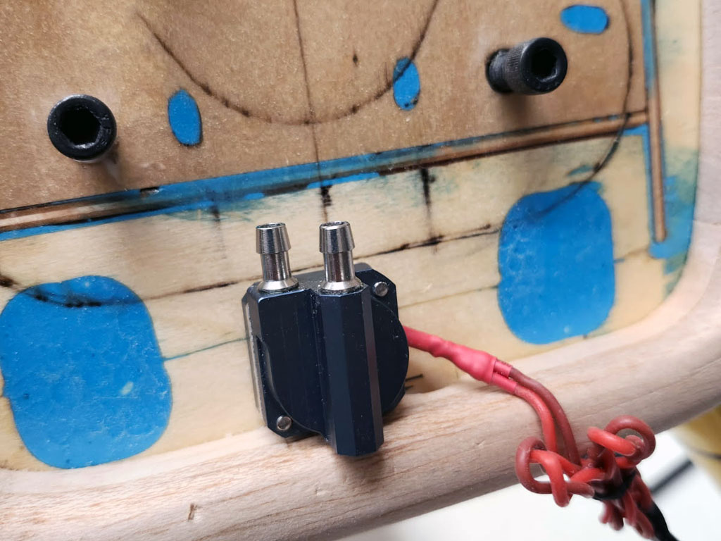
- TMC M400k-v pump installed with fuel niples facing up
Is confession is good for the soul?
Further to the pump, I must confess to making a mistake when I ordered.
Fuel nipples
The folks who offer these Micropump units offer it in two nipples sizes, small and large. The small is perfect for 1/8-inch fuel tubing. Point being, I've plumbed for 1/8-inch tubing and bought the large nipples - oops!
Fortunately, the Tygon tubing is sufficiently forgiving we can force the 1/8-inch tubing over the barb without heating - but - word to the wise when sourcing your pump if your engine calls for one, eh?

- 1/8-inch Tygon tubing forced over large fuel nipple
Storage hooks
So after confessing to a predilection toward large versus small fuel-nipples resulting in ordering the wrong pump fittings, here's what else I've screwed up recently.
I like to use padded wall-hooks to stash fuselages in my workshop. I buy them at Lowe's where they're meant for garden tools. The hooks are padded with foam and I like to use these to store fuselages by hanging them on the wall from the horizontal stab. Major point being, I grabbed a new hook like usual, and found a convenient open spot on the wall for another fuselage, and ran a screw.
Note; while they have a place for three mounting screws, I use just the one because I'm going into plywood behind the gray wall covering. If you're going into drywall, then you either have to hit a stud to pull off this trick off using just one screw, or you should use three drywall anchors. Heads up!
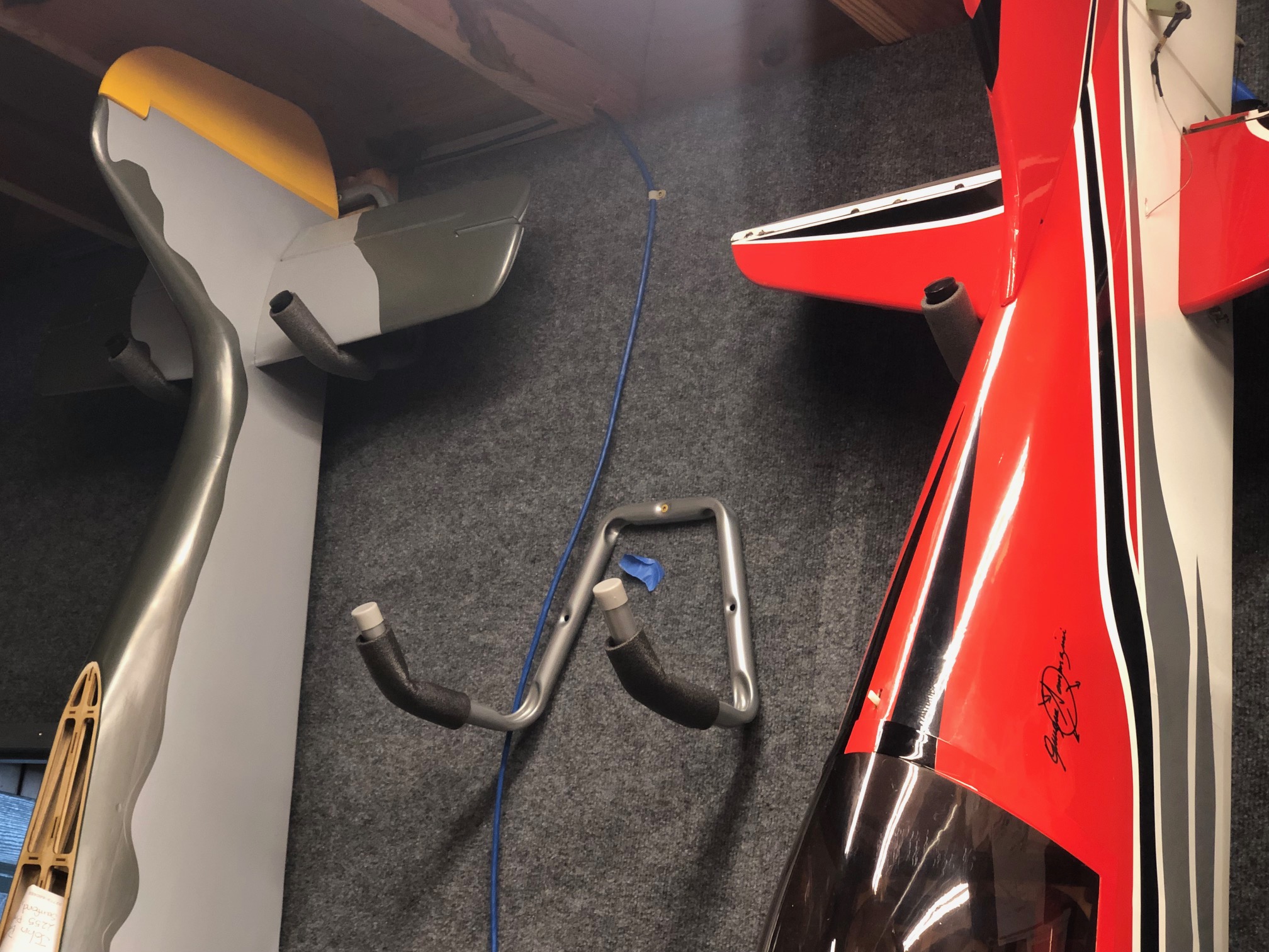
- Padded wall hooks from the hardware store for storing fuselages
Anyway, after fiddling with the best position for the hook, I drove a screw home and hung the Stearman fuselage. There it was flanked by the good company of a Top Flite 1/5th scale Fw-190, and a Flex Innovations Mamba 70.
Next, I turned my focus to other things leaving the Stearman awaiting me to have attention-span to devote to readying it for flight.
Well, in the words of Lee Corso . . . no so fast! Here's what went wrong.

- Fuselages suspend by the horizontal stab on padded steel wall hooks
Fast forward a couple months and a problem reared its head. Thing is, instead of first inspecting the stab-structure thus ensuring it would be adequate for the load - like I should have - I merely assumed it would work as it has for many other models. In this, I was sadly mistaken!
As a consequence of my hubris, the mass of the model broke the lightly built stab leading edge in three places. Thus proving, on the odd occasion, I can really be a doofus!
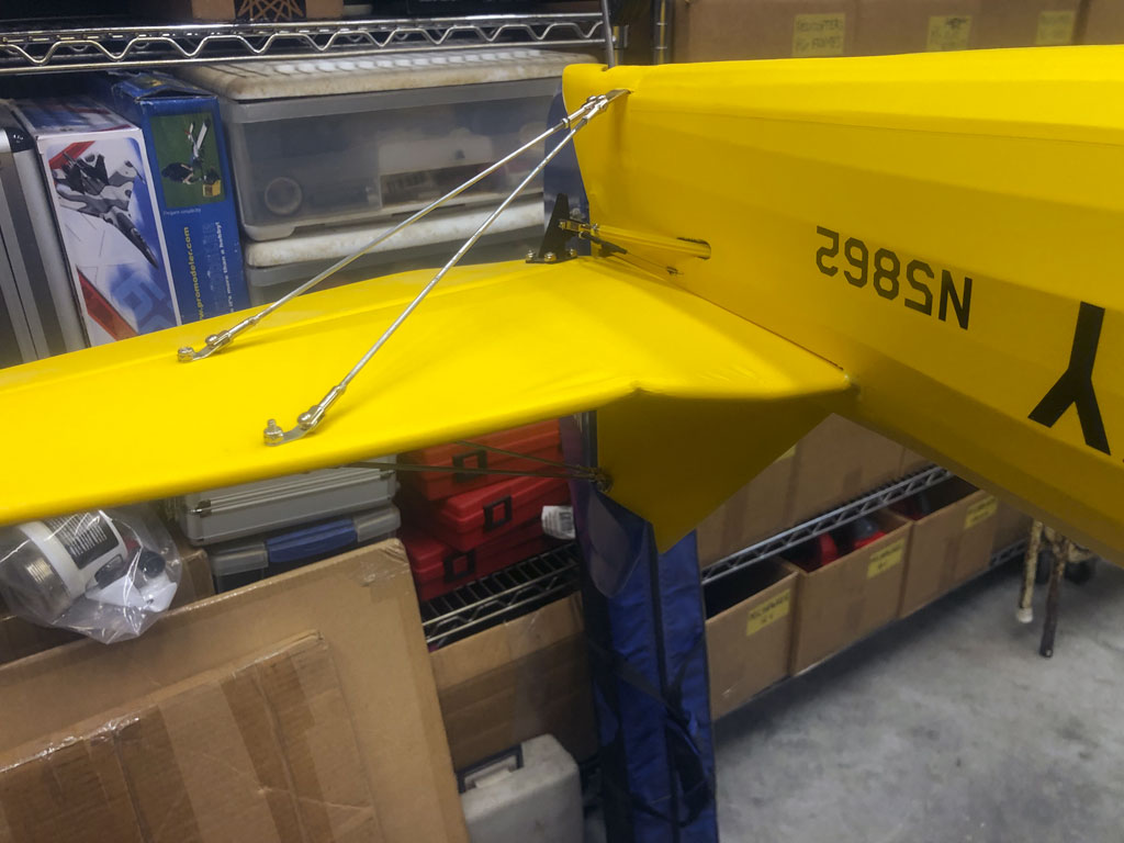
- Damaged leading edge - fractured in 3 places
Interestingly, the other side's leading edge was relatively undamaged. Yes, dented, but in comparison barely dented!
Note; port side dinged inboard of where it's supported by the support struts.
- Barely dented leading edge of the other side's stab
puffing
So it's my suspicion the dented balsa on this port side could posibly be injected with water. For those unaware, this is a technique for wood repair using the tiny needle meant for an insulin syringe.

- Tiny gauge needle used for dispensing insulin works great
Basically, after penetrating the covering and injecting the dented wood with water, hitting it with a hot MonoKote iron sees the water expand to create steam and presto, the dent instantly puffs out - thus, erasing it.
Of course, in fact, the wood fibers remain damaged. Thus, it's a judgement call on if this is done in an area that's cosmetic or structurally sound. Know this, it's my experience massaging said previously dented surface with the hot iron makes the damage indiscernible almost 100% of the time.
On repairing the damage
Before continuing with the repair, and in my defense, usually there's no issue with hanging a fuselage this way - but - recall these models tend to come comes out tail heavy. And Nick Ziroli is nobody's fool. Means he builds them to fly, not crash. Put another way, lightly built! Too lightly in this instance.
Note; it didn't fail immediately. Took a bit of time. Now clue how long but within a matter of weeks. Anyway, the stab leading edge failed and it was my fault for not confirming the structure was strong enough.
In this next photo the covering has been removed and the stab's leading edge has been replaced with a new piece of balsa.
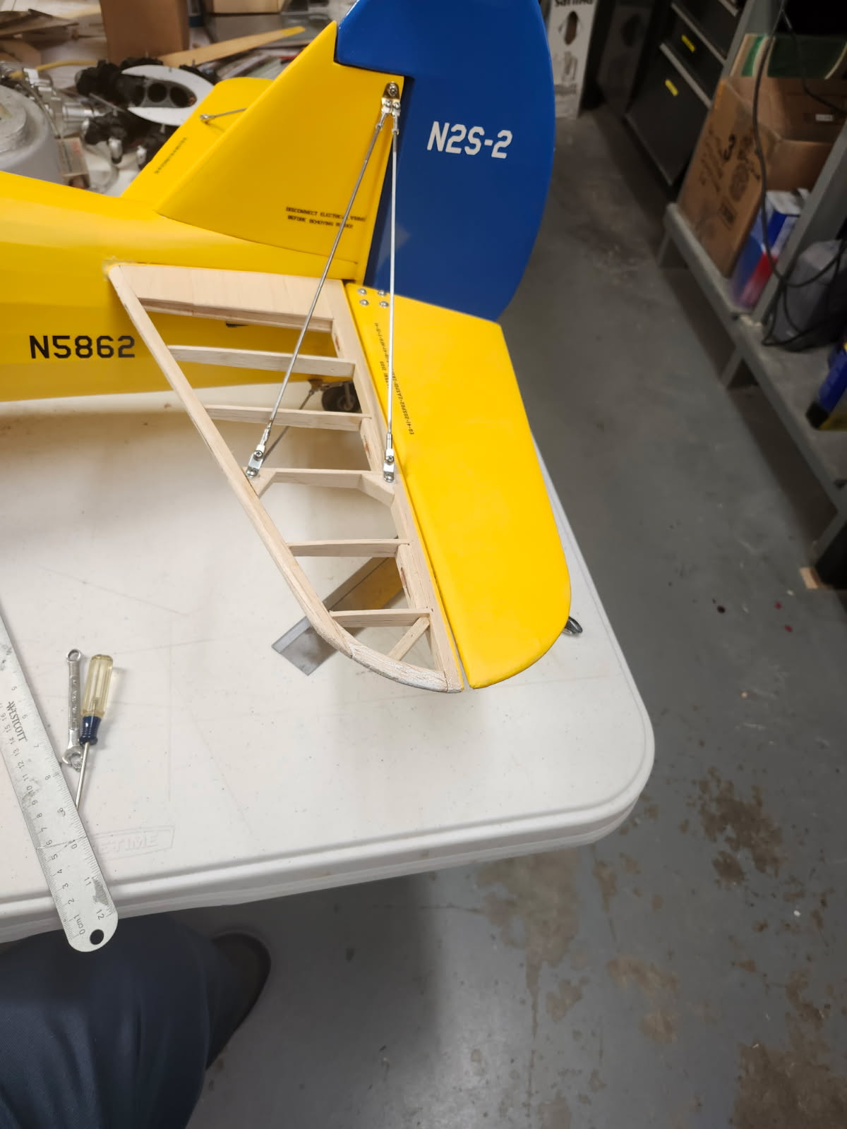
- Crushed stab leading edge replaced with new balsa
Anyway, while it's naked for repair, a spot of reinforcement was deemed a good idea. This through the judicious application of a bit of carbon fiber pultruded 5mm tube (1mm wall). Stout stuff, weighs but a couple grams.
In this photo, it's already embedded in the leading edge with epoxy and merely awaits a bit of Stits SuperFil.
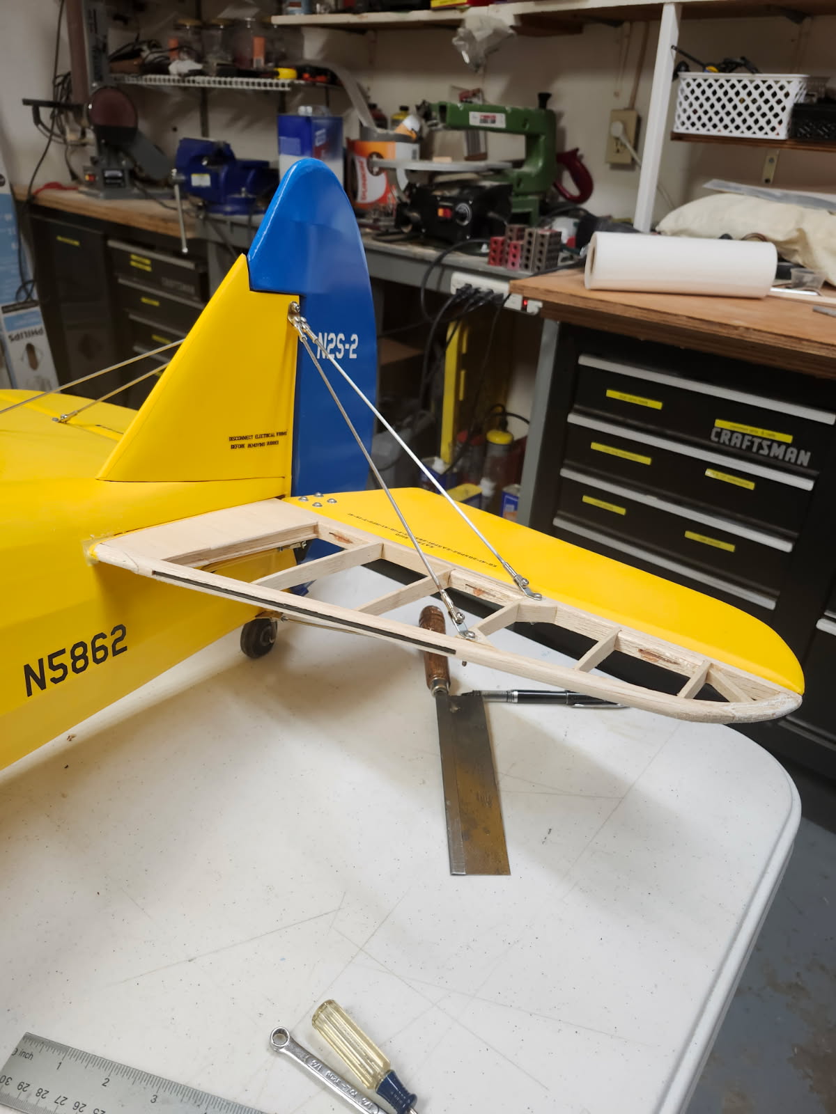
- 5mm pultruded carbon fiber rod as reinforcement
Then here's the other side already filled with SuperFil and sanded smooth ready for covering. Note the added gusseting to help better spread the load.
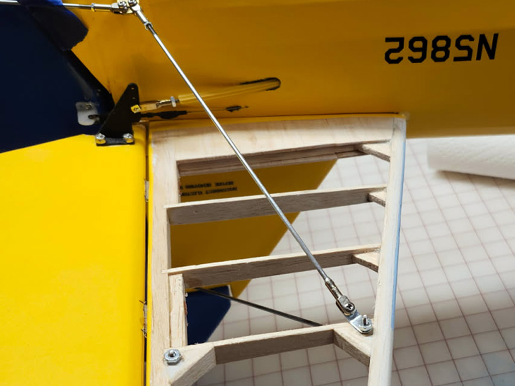
- Gussets add enormously to the strength with little weight
And if you're wondering, cutting back the Oratex almost to the hinge line allows for the stab to be re-covered without much in the way of drama.
Note; leaving the steel guy rods in place ensured the alignment of the stab remained perfect during the repair.
- Covering material left near the hinge line
And it's a wrap, new Oracover shrunk in place and it's like it never happened!

- Horizontal stabs ready for flight once again
Small details
So if you noted in earlier photos the nomenclature (lettering) was partly obliterated in the process, all is not lost. Getting the old ones off proved easy enough after lifting an edge with the tip of a No.11 X-Acto blade. Peeled up nicely and resulted in a good surface from which to come again, fresh.
And yes, Callie Graphics to the rescue with fresh nomenclature.
Note; One wrap of 1/8-inch frog tape to establish a good line.
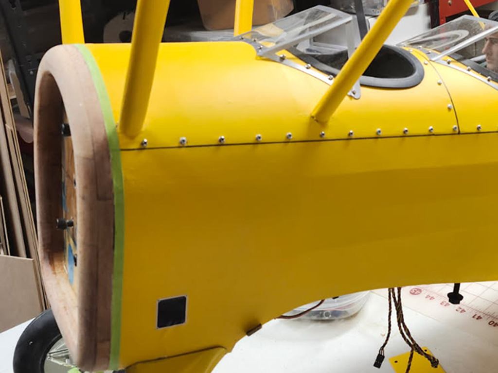
- Forward fuselage again ready for nomenclature
The nest step is to prime to cowl ring before shooting silver color. For this bog standard cellulose lacquer gray primer from the automotive parts or hardware store fills the bill nicely. Lays down nice, dries quick, perfect!
As usually, the real work involved is the masking. Wheels and struts were easy, just bags and tape. But for larer surfaces, there's no good substirute for brown paper. Ditto the cabane struts, which are tedious.

- Rattle can gray primer from the auto parts store
However, the final results are sweet. Once the paper and tape gets removed and you see how the silver paint just looks right, then it's a no brainer to go to the effort. In this next photo of the Ziroli Stearman firewall and nose ring, while it's now painted silver also includes a subtle detail. What? Eyeball the the 1/8-inch stripe of black paint between the silver and the yellow fabric. It's an easy to overlook touch that halps makes the silver firewall pop!
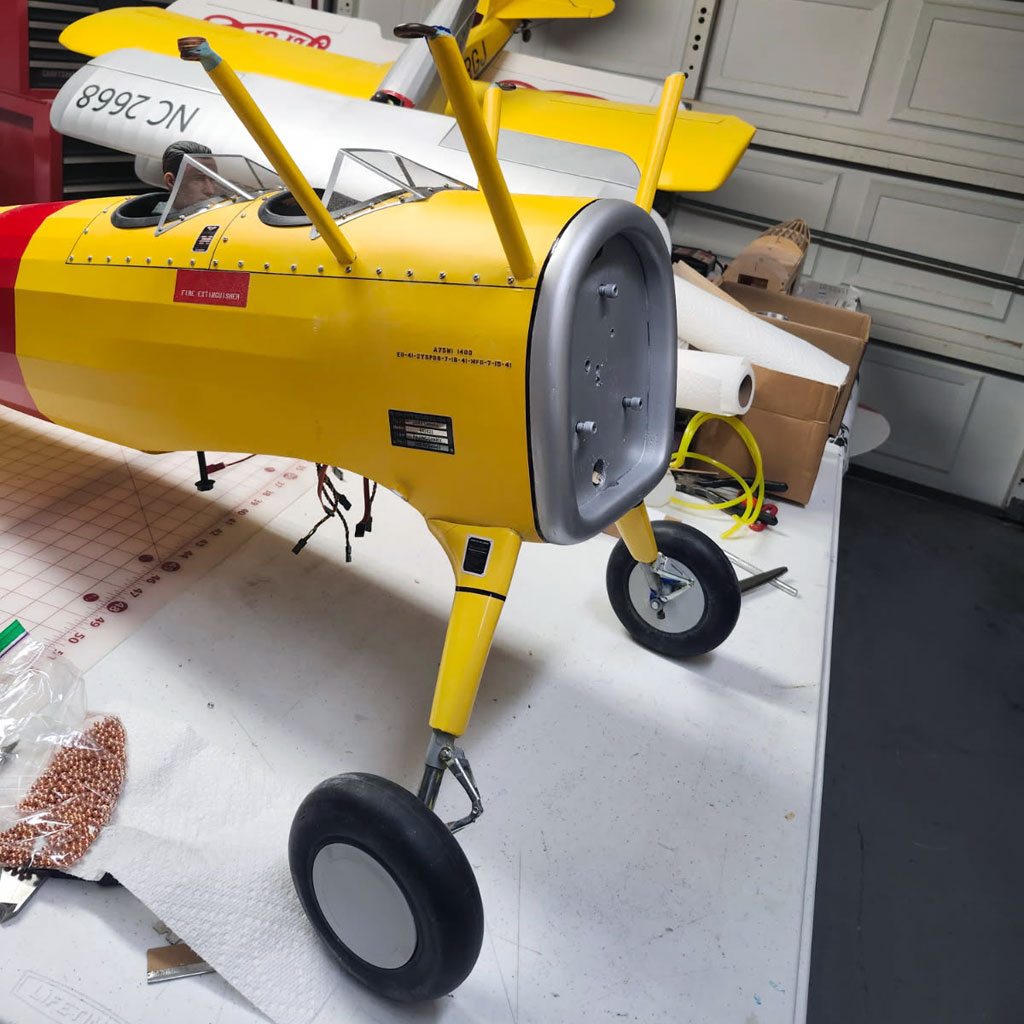
- The silver paint with black trim makes the whole thing look 'right'
So earlier we touched on switches and odds. I said I like dual switches for avionics whilst relying one battery pack. I also can, but don't bother, with dual switches for the ignition.
Reason for this has to do with odds, again. Basically, I am sufficiently confident in my skills as a pilot that if the ignition switch craps out, for me it just means a dead stick landing instead of a guaranteed crash. Reason for this is experience. Totally different conversation if your sole avionics switch takes a crap because then you're just a spectator as skill plays no role. That, and I don't have anywhere to tie in a second switch with an ignition box.
Now let's touch on specifics.
Switches - practice vs theory
For this model, I used two different types of switches. And neither is the slide-type I shared at the beginning of the article.
Instead, we used a dual illuminated rocker for avionics, plus an over-center toggle switch for ignition. We offer all three types (and some variations on the connectors, e.g. DuPont, EC3, and XT30) within switches on the website, just follow the link.
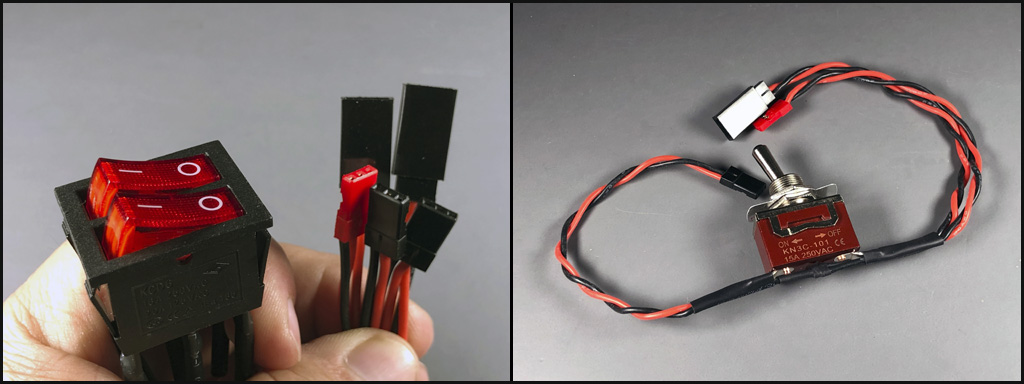
- A dual illuminated switch and an over-center toggle switch
Anyway, the dual illuminated switch is a bit clunky to mount because there are two switches housed in the one. Basically it's not tiny and easily hidden. Means you need a bit of space to pull it off. And FWIW, I especially like this type switch with some scale models and most XA-models. This, because a latch lets you lift off the canopy and expose the entire forward part of the fuselage up to the firewall.
An example is this gorgeous TopRC Zero. One battery pack powers ignition and landing gear, the other battery pack powers the receiver and servos. Both are routed through ProModeler dual illuminated rockers!
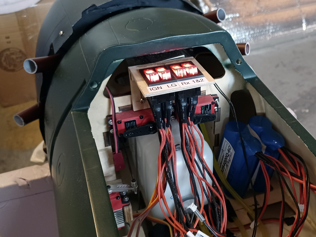
- Dual duals, one for ignition and landing gear, the other for avionics
So the above model is one thing, plenty of space for mounting a switch. However, with other models, like this Stearman build, you need to have a plan.
As a reminder, tandem aircraft are flown from the aft cockpit. So the plan for this model is to mount a pilot figure in the aft cockpit, but no pilot in the forward one. Reason for this is to shave a few ounces off the AUW (all up weight). But I'm not so desperate to save weight I'd go with no pilot figure because I believe models look kind of stupid with no pilot figure. However, one is an acceptable compromise.
Anyway, the cockpit floor of the forward cockpit is perfect for mounting switches because it's both semi-hidden from view by the upper wing, whilst at the same time, remaining easily accessible. Ended up like this!

- Dual illuminated rocker for avionics and over-center toggle for ignition
Wrapping up
We had a bit of fun writing up this caseSTUDY article. To begin, it was built by a truly gifted expert. And it was modified to accept the UMS 9-115 radial by the same fellow. In taking the opportunity to showcase what's involved in decisions involving model aircraft engines, we shared the detailed how to of making calculations as they relate to the CG of the aircraft. And we touched on equipment alternatives and what leads to selecting one set of servos versus another.
If you have questions, reach out and we'll try our best to help you understand.


