
Introduction
So the phone rings and it's the handsome guy in the above photo. He's Matt Fornefeld of Georgetown, TX and he's a long time customer. Says he's calling for advice regarding servos for a build he's planning based on using Hosteler's Plans of the Cessna 195 from a National Balsa laser cut kit. This, instead of cutting the parts himself.
Thing is, because nothing he builds is 'stock', I know we're in for a treat if I can just get him to take photos! Can't always because once he gets into the flow, taking pictures is the last thing on his mind. Meanwhile, though, I'm a bit perplexed because I'm pretty sure he doesn't really need my advice for servos. Why not?
Heads up, servos pay the bills, brief spiel incoming - PageDown is your friend
Servos
Why doesn't he need my advice? Simple, it's because he's already outfitted 6-8 models with our servos. That, and by now he knows me well enough to reliably predict what I'm going to suggest for many warbird and sport models going 25-30lbs and spanning in the range of a 84-110-inches.


This, because for almost any sport or scale model on the planet, I'm usually going to tell folks they'll be well served (and at the same time save serious money) by looking at our standard size DL-series servos. The ones built in a hybrid case (polymer and aluminum) which range in torque rating from 90oz-in to 415oz-in.
Since we also produce bespoke hand built brushless servos within an all-aluminum case ranging from 505oz-in to 1155oz-in, then the question is; will I ever steer a guy into a set of these for a scale build?

Answer is, a definite maybe, sometimes. But it really depends not just on the model but also the engine, and how he'll fly it. Take for example a P-51 equipped with a Kolm 3-cylinder IL230 where he says he and his pals engaging in a spot of air racing where the model goes 37 pounds? Then due to weight, higher airspeed, and how it's be flown (specifically the G-loads pulled at the pylons), then yes I'm quite likely going to guide him to an alloy case servo.
But plenty of Mustangs get a DL-series servo recommendation.
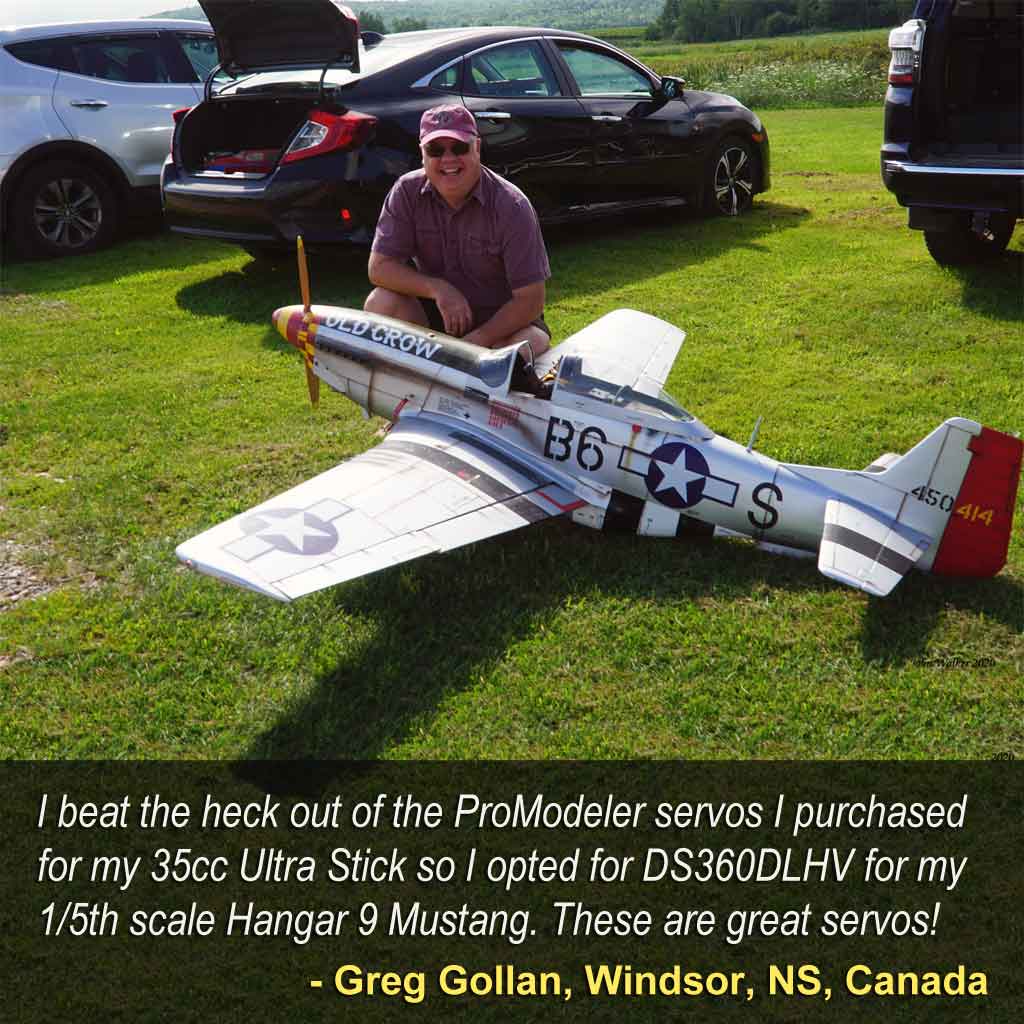
But for a model like this Cessna 195? It's my judgement a set of DL-series servos will be perfect. And look, ask around, our reputation isn't about guiding folks to more expensive servos to generate bigger sales tickets, but instead, it's about, What's the right servo for you? So here's a great example, a fellow who bought an Extreme Flight 85-in wingspan Legacy Aviation Muscle Bipe model.
He said he planned on using one of those gorgeous Saito FG-90R3 radial engines for it. So he called to inquire about servos and what I suggested cost a good deal less than what he had budgeted for it, servo-wise. How do I know? Simple, because he told me!
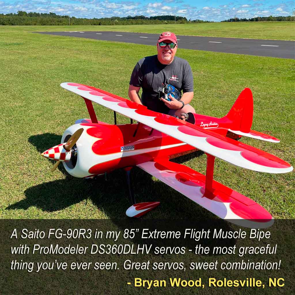
Basically, it's our opinion your servos need to match 'your' desired schedule of maneuvers versus the model's capabilities!
Note; the vendor of this model recommends servos and servo arms - but - for how I suspected this fellow planned to fly it based on engine choice and how he said he liked to fly, it didn't make sense to spec pricey servos more suited to XA-maneuvers.
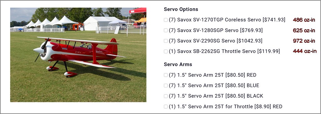
Major point being, and just so you know, I'm 'very' familiar with how the typical Extreme Flight customer outfits their model, servo-wise. They basically want fast, powerful servos to permit rifle rolls, walls, crankshafts, e.g. XA-type maneuvers. This, as opposed to the typical airshow-type maneuvers this fellow described wanting to fly (loops, rolls, Cuban-8s).
Minor point being, this fellow was primed to go with our top shelf DS505BLHV brushless servos, maybe even DS845BLHV if he was a gonzo nuts type pilot (the ones out inventing maneuvers). Thing is, because of the engine he wanted to use, I was pretty sure he'd bought the model for the looks instead of evil intent.
Like it would be a totally different story servo-wise had he said he planned to install a DA-85 and throw it around hard, take my meaning? Same model, two totally different use cases! So outfitting it for the latter mission would just be pissin' away money because the only place he'd feel the difference would be in his wallet.
Anyway, a few questions later I was satisfied I knew how he planned to fly and made my recommendation. He opted for servos from our DL-series even though the Muscle Bipe is quite a serious XA-type model. Minor point being, he trusted my judgement so when I recommended a set of DS360DLHV it helped him save some serious coin!
What's more, the same holds in spades with the Cessna 195 because even if he plans to fly it like he stole it, due to the size of the control surfaces, it will 'never' be doing XA-type maneuvers. Why not? Simple, the control surfaces just aren't large enough! Means you could put our 1155oz-in servos in it and it wouldn't matter in the slightest just because there comes a point where there's enough servo for the job.
Anyway, if you're new to us, we offer servos in several classes, or sizes. Standard-class is the one on the right. And within the standard-class, we offer five different series ranging from 90oz-in through to 1155oz-in. Which is best? As always . . . it depends!
But know this; DL-series are the servos that turn more first time buyers into loyal fans than anything else we offer.
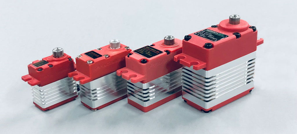
- From left to right, our 9-gram class, then micro, mini, and standard-class
Note; if you have experience with the ubiquitous Hitec HS-5645MG, then because theirs and ours are very close to the same size, then you already know what we're talking about with the term 'standard-class' servos.
This close up photo shows the guts of a DL-series servo. What's more, it's the type photo other manufacturers won't share. So what makes these servos so good beside using the exact same potentiometer as we use in our most powerful servos is you still get the good stuff used in our lineup of brushless servos.
Talking about a spot welded stainless steel gears. Bronze reinforced plastic (where the gear shafts are fitted to the polymer case sections). 10 Allen-head bolts securing components together instead of 4 Phillips. And a center case, which cools much better because it's aircraft aluminum, into which we machine cooling fins! Added to which, you get 13 seals and o-rings to protect against water and smoke oil intrusion. Plus - what our government contractors value above all else - you get a servo meeting eight MIL-STDS.
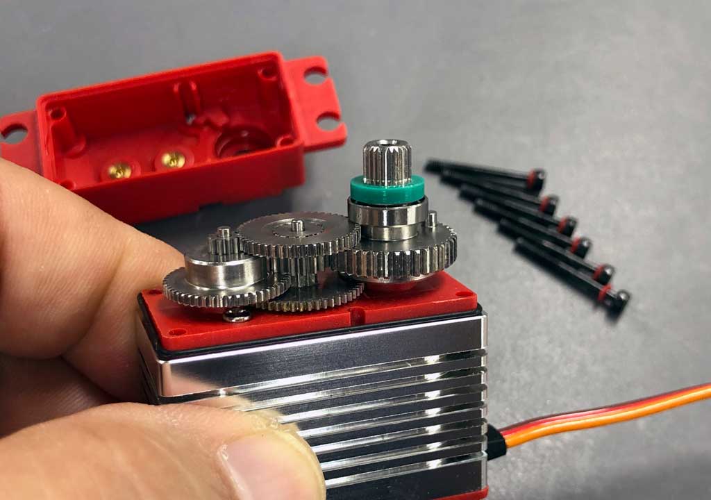
And while we're on the subject, I'll give you Hitec makes a decent servo (world's best selling servo), but is anyone surprised I think ours are better? Curious why this is? Eyeball the comparison photos in this article!
That's it, we're largely done yakking about servos . . . now back the 195 build
Cessna 195 - RDS
Meanwhile, and back to the Cessna 195, instead of putting together an ARF, Matt's planning on building a model the old fashioned way, one piece at a time! So we're going to share the pictures he sent me - but - it's important that you not gloss over them. My advice is you really should look closely lest you miss something!
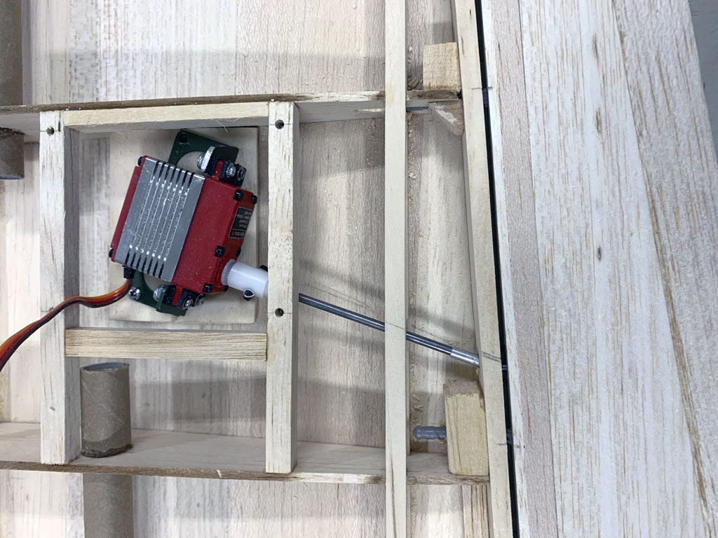
A good example of why is this next photo. Ignore the servo, and instead, look at how it's connected to the rudder. He's used an RDS (rotary drive system) to move the surface. Basically, as the servo rotates back and forth, the 45° crook at the end of the linkage rod wiggles up and down. And when inserted into a hard-sided pocket built into the control surface, then this 'wiggle' makes the control surface move up and down.
It's an ingenious system! More later.
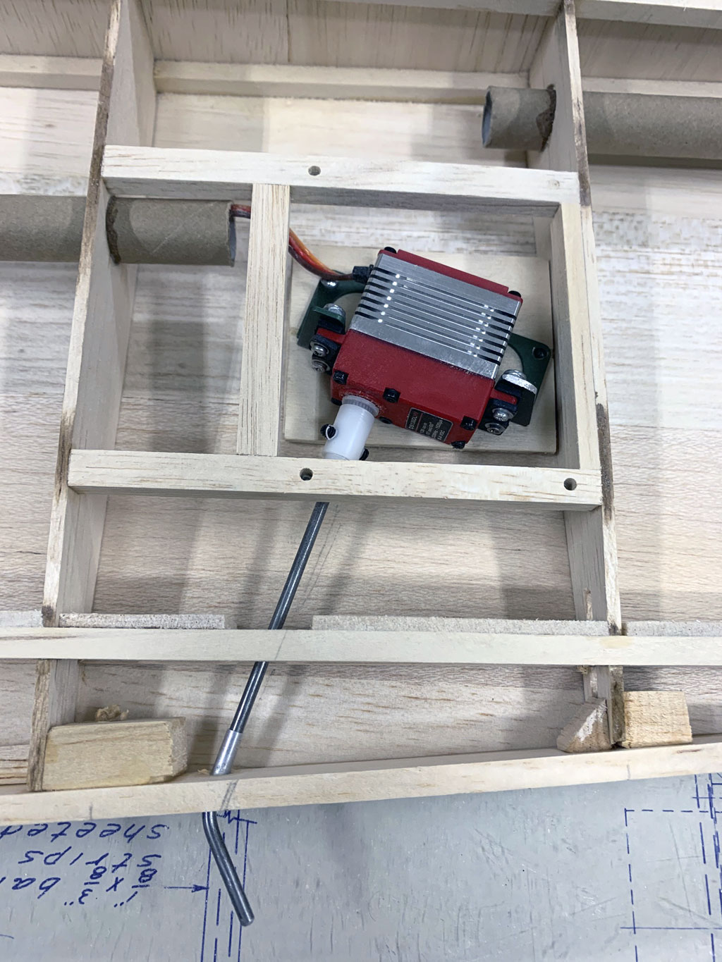
- The rotary drive coupler makes it easy to hide control linkages
So the RDS mechanism is what lets him 'hide' the control linkages. But know this . . . Matt never mentioned he was going to use RDS on the phone, else I'd have mentioned the fact we make two different sizes of RDS couplers. Unfortunately, and as a consequence, he used someone else's RDS components - sigh.
Anyway, this can't be helped now (so the consolation prize is telling you about it, instead). We'll touch on this later.
Meanwhile, and circling back to the call, if Matt didn't need my advice about servos, then why did he reach out? After all, we have a decent website with plenty of information so it's not like he really 'needed' me for anything. Honestly? I think he just wanted to yak about his new project. And because I love nothing better than talking airplanes, we settled in to catch up.
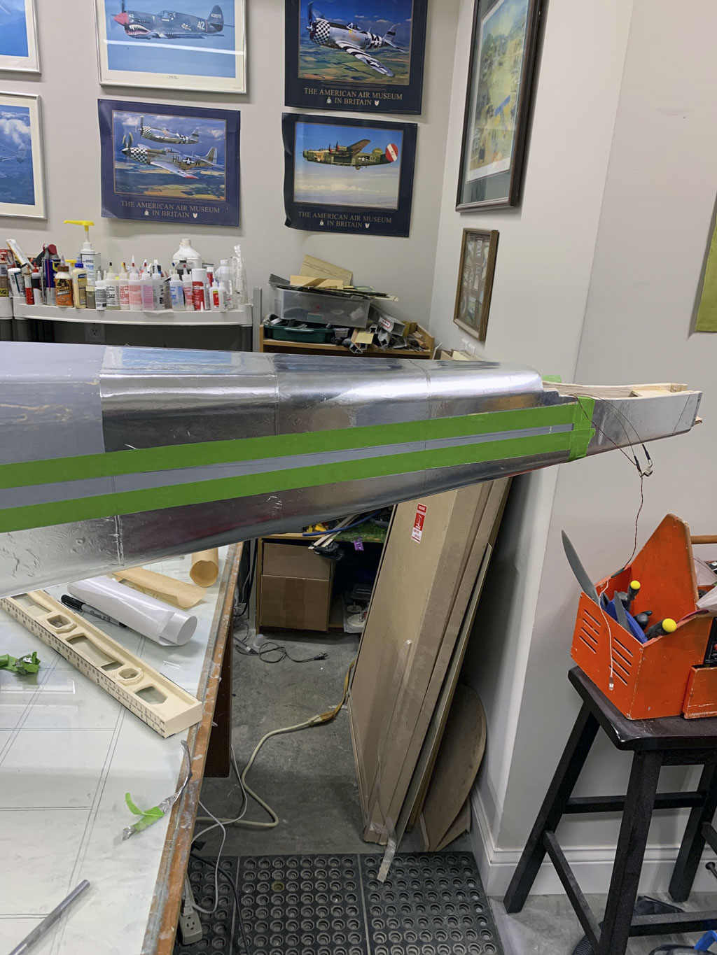
Along the way I learned of his plans to finish the model in aluminum. Yup, if you look again at the article's hero photo and eyeball the model more closely. That's not silver paint, it's actual polished aluminum! Here, I'll save you the trouble to going back to look
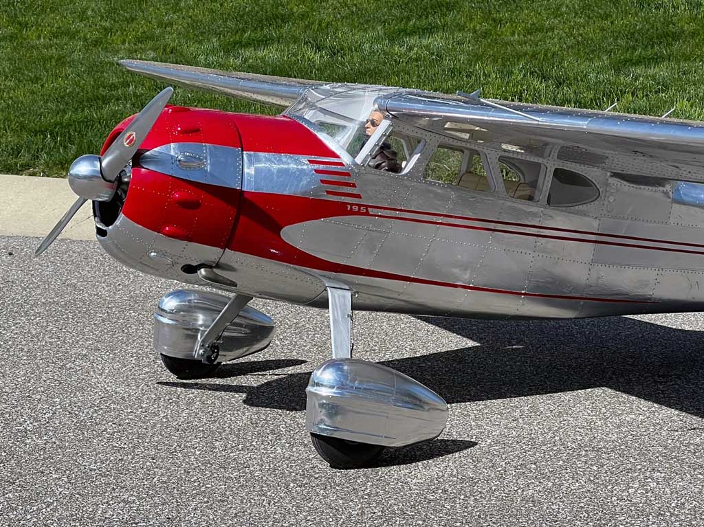
He also said something about fully dressing out the cabin interior, which we'll get to in due course. But of special interest to me (because I'm queer for engines) was talk of buying a four-stroke radial for the model. And not one for glow fuel, but a UMS 'gasser' on ignition (e.g. burning gas/oil premix).
Honestly? Now he really had my attention! Anyway, we'll touch on all these subjects (plus a few more). And all supported by great photos.
Photos
So speaking of photos, once I brought the subject up, he quickly bought into the idea. And no, this doesn't require an expensive camera, just using a phone as you go. Anyway, if you're interested in learning more about using a phone to share photos with us, maybe review these two articles.
Point being, he and I laid out the groundwork . . . if he took and shared photos with me, then in turn, I'd use the photo sequence and write an article. Since he and I both kept up our end of the bargain, this is what you're reading, now!
Note; the idea was never to get bogged down in one of those glue stick-A to stick-B type articles. Instead, it's to show an abbreviated build. One where we merely slow down to eyeball interesting stuff. What for? To help guide the next guy thinking about undertaking one of these Hostetler Cessna 195 builds. Like who knows? Maybe it's you!
Anyway, and in a genuine stroke of luck, because in addition to being a gifted builder, Matt also has a flair for photography it means we received some great shots. Like go back and look closely at the RDS linkage in the previous photo. What's easy to overlook is how he bushed the RDS- shaft with a bit of aluminum tubing (where it goes through the trailing edge).
Major point being, Matt's the kind of builder who pays attention to the small stuff, the details. So in what follows, it's in the details where you'll find the gold - but - only if you don't blow past his photos!
Accessories
Anyway, while I said it's not a servo article, kindly allow me to mention these two accessories. These are what you'll want on hand if you follow in Matt's footsteps and decide to use an RDS to the control surfaces of your build. These include RDS couplers themselves, plus side mounts.
The RDS couplers come in two sizes. They're both 25T splines - but - the small one is for the 5M spline (as used on our DS115CLHV wing servo, nominally 5mm diameter). The other is the usual 25T spline as found on our servos (with a 6mm output shaft).
Note: both are drilled with witness holes - these so epoxy has where to leak out (visual confirmation it's not a forgotten dry fit).
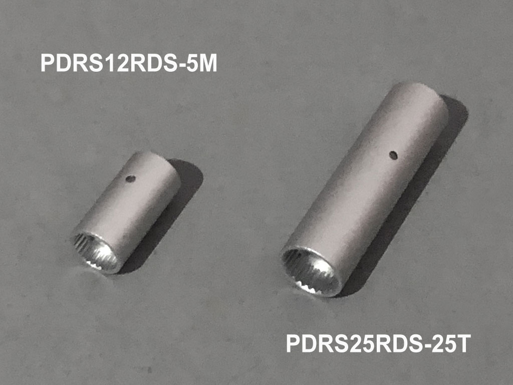
- Close up of RDS systems for both ø5 and ø6 diameter splined shafts
And in addition to the drive couplers themselves, we offer side mounts. These are CNC machined from a solid billet of 7075-T6 aircraft aluminum. We offer them in four sizes to suit our range of servos. They include mounts for our tiny 9-gram class, through micro, mini, and of course, standard-class servos.
The sidemounts are supplied with top shelf Allen head hardware.
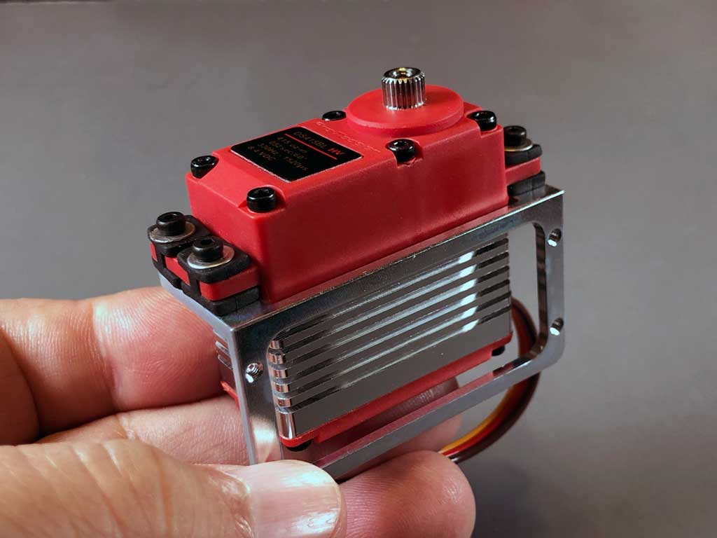
- ProModeler DL-series fitted to part number PDRSM-standard
So because I've artfully broached the subject of these widgets, let me tell you what I never got to tell Matt; what's different about our RDS is we went overboard and used alloy instead of plastic.
They're machined of 7075-T6 aircraft aluminum (which rivals 1018 steel in terms of strength) and broached in-house. So in this next photo, note how an 5M RDS adapter accepts a 5mm shaft. But in the alternative, you can gin up an adapter to transition to wire (as Matt did). We tell you how in in the product description on the website.
Note; carbon fiber tube (5mm OD, 1mm wall) is readily available on eBay and fits perfectly.
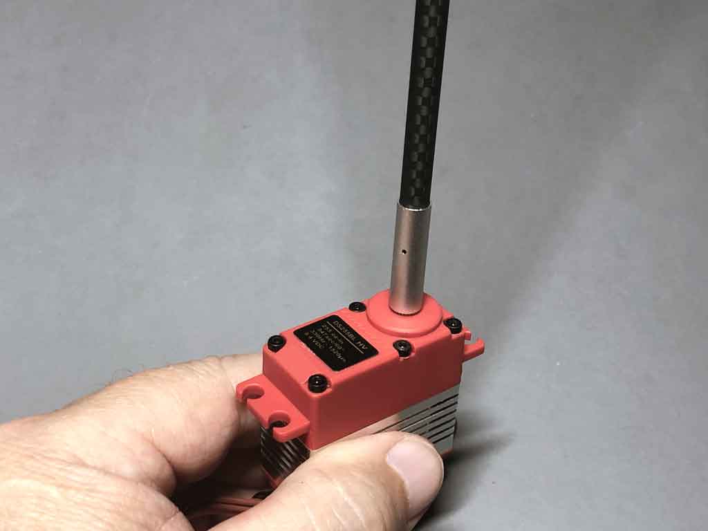
- ProModeler PDRS-RDS-25T accept up to a 5mm tube
Process
We're sharing construction photos, equipment installation photos, plus photos showcasing some of the little stuff. Like brake calipers, and of course, the cabin interior. Plus a bit regarding the engine installation (and that fabulous finish). And while we're not going into excruciating detail, Matt shares enough photos of the process of the aluminum alloy cladding that I've ordered some to have in stock (for me, personally, not as ProModeler).
Honestly, I enjoyed these photos immensely (and hope you do, too). And what I really hope this article does is fire up the little gray cells about application of this aluminum finish you may have in mind. This, because there are lots of models, which are candidates for this treatment. And this brings us to what he used.
Flite-Metal
So if you look at this next photo you see a bit of a nifty product created and brought to market by a fellow name of Ed Clayman. He developed it over the course of years of trial and error of looking for the 'right' aluminum alloy, for it to be workable, the right thickness, storable, and with an adhesive to produce long terms result. Took a while but he got there.
He markets it as Flite-Metal, and not to jump ahead but here's a piece stuck to the bottom aft part of the fuselage.
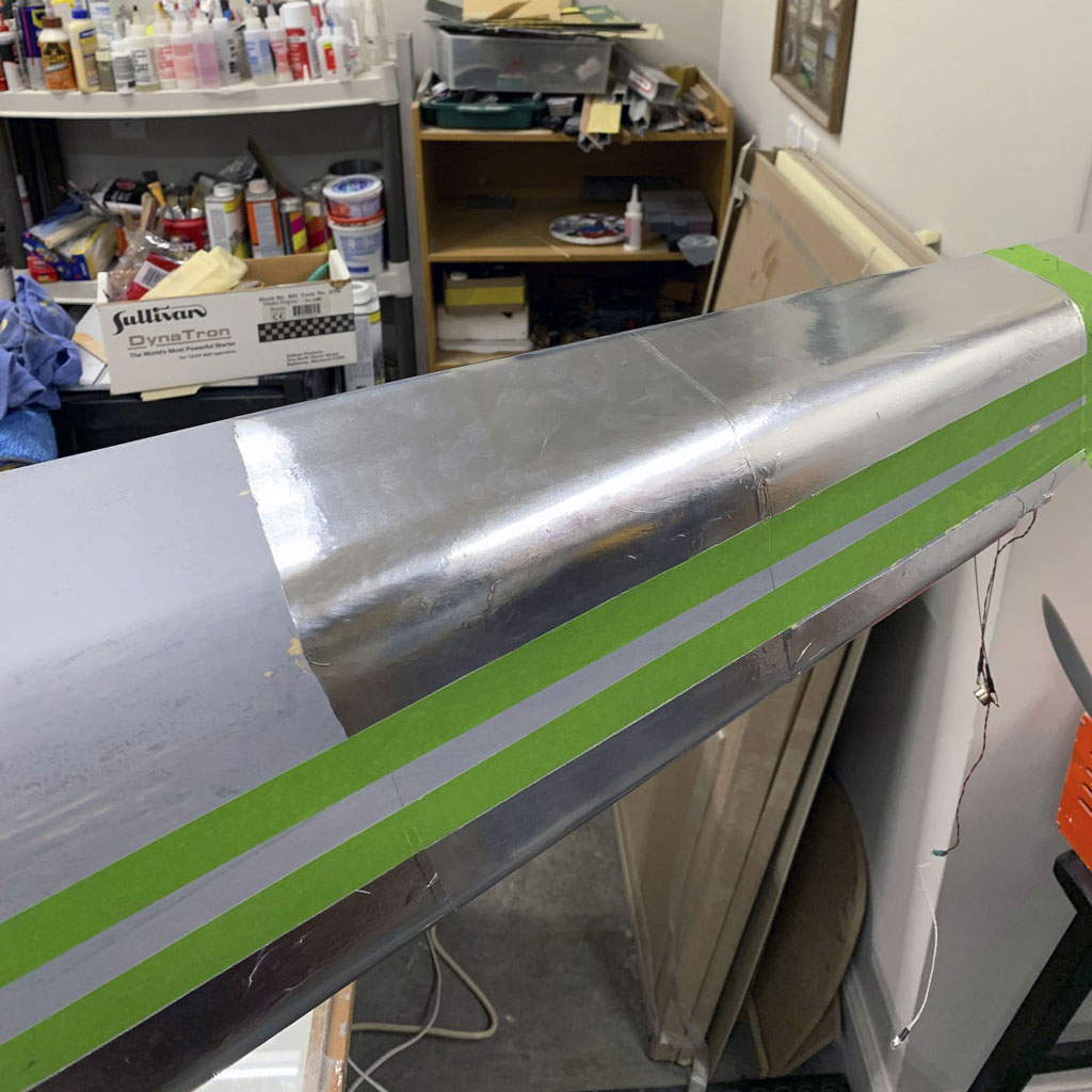
- Genuine aluminum Flite-Metal looks real because it is real
So if you missed it, Flite-Metal is genuine aluminum, with adhesive backing. Ed offers it by the foot on a roll and scale mavens around the world use it to replicate aircraft finishes using real aluminum alloy.
Note; Ed also offers inexpensive burnishing tools and rivet wheels to help get the job done.
Me? I appreciate Flite-Metal for what it brings to the game because nothing looks more real than the real thing. Anyway, there's nothing in it for me (in exchange for sharing this information). It's just a well deserved shoutout to Ed for Flite-Metal because it's a fantastic arrow for our quiver of building and finishing tools!
Next, before proceeding to the build, a bit of full scale background - an appetizer so to speak - to finish setting the table.
Background
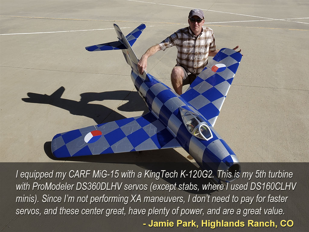
So I mentioned thinking Matt already knew what he wanted servo-wise. I was right. However, as to why DL-series servos instead of something pricier in our lineup, perhaps something offering higher performance? It's for the same reason I guide virtually 'all' scale modelers to DL-series servos; they're plenty strong, economical, and center great.
Point being, faster servos are silly for something that'll never perform XA-type maneuvers, which is where fast servos shine. In fact, and quite honestly, about the only place you'd feel the difference with most scale models equipped with faster servos is in your wallet.
That said, if you have more money than God, and expressly want info about top of the range brushless servos for this kind of build, then eyeball our BLS1-series. Moreover, even if this doesn't describe you, these articles may be of interest:
Anyway, Matt gets the concept, and so does this next fellow. Reason for this photo is Jamie expresses what I want to say not just better than me, but in far fewer words!
About the Cessna 195
So if the 195 doesn't ring a bell, it's perhaps better known as the cantilever wing Businessliner, which Cessna introduced to the executive transport market immediately after the close of WWII. The big idea then being to capitalize on returning pilots. Ones, who having learned to fly on Uncle Sam's dime, were going to form the backbone of a great new business opportunity by flying about the country instead of driving.
Cessna's obvious hope being to put Wichita, KS on the map next to Detroit, MI. Sadly, instead of America capitalizing aviation products alongside the big three's autos (thus forwarding the economic interests of the USA), the FAA under the guise of safety has slowly strangled general aviation with red tape thus, leading to the loss of hundreds of thousands of jobs. An entire industry gone poof because of bureaucrats run amok. But I digress.
Anyway, back on the subject, this YouTube video gives a really good sense of what the Cessna 195 aircraft is like to own and operate.
Regarding Cessna 195 plans
Anyway, a reknown model airplane designer name of Wendell Hostetler drew up plans for Cessna's 195 at 3-inches to the foot (quarter scale). Since the full scale aircraft sports a wingspan of 36-feet 2-inches, 4:1 works out to a nice size model at 108.5-inches (9-feet one half inch). Basically, the model is big and has good presence, but it's not so big it's a nuisance to store and transport.
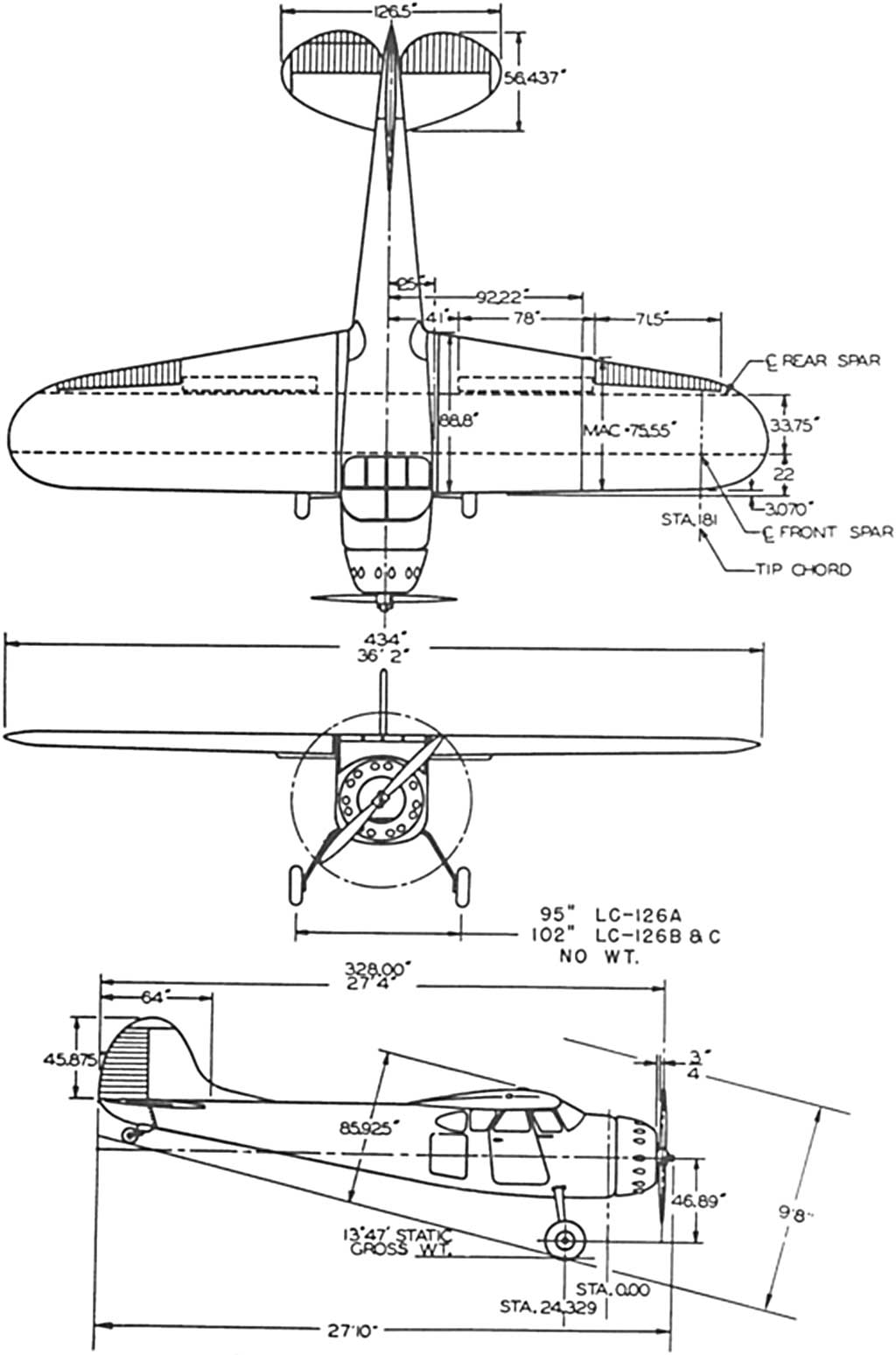
- Eyeball the small split flaps in the plan view of the wing
Engines
When it comes to selecting the engine, displacement-wise, for what amounts to a high wing sports model, this design was about perfect for one of the dominant engines from back in the day. Speaking of the famous Quadra 35.
Basically, the Quadra 35 is the engine, which defined the market for burning economical gasoline premix instead of glow fuel (methanol, alcohol, and nitromethane) beginning in the late 1970s. And guess what? They're still plenty of models flying with this engine!
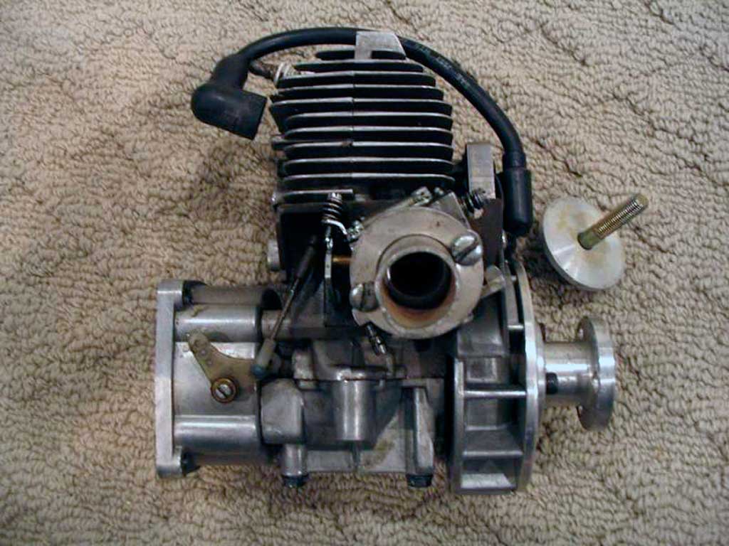
- The engine which started it all, the Quadra 35
Of course, these days battery-ignition engines have supplanted magneto-ignition engines like the old Quadra. Means while most of these being built today are powered by a similar displacement engine, it'll be more likely to be something like the smooth and powerful DLE 35, or maybe the heavier 55RA. Regardless, it'll be using a battery-powered ignition module. And yes, more and more are built with a 12S electric setup, instead.
Anyway, and entirely due to the fact the 195 has a relatively short nose (because Cessna designed it for a heavy radial engine), I've seen these models flown using engines as large as the DA85. Overkill power-wise? Oh heck yes! However, the reason has entirely to do with this old modeler's adage . . .
- I'd rather install a bigger engine than use lead to get it to balance!
And hewing to this philosophy in spades, engine-wise Matt opted for a gorgeous UMS 5-75 radial engine! This smooth running and comparatively massive engine is perfect for this model. What's more, it offers up a sound that must be experienced to be believed.
Note; if you, too, develop a hankering for one of these radial engines (I did), then they're sold by Adrian Ciulei out of Fort Lauderdale, FL. And if the name's familiar it's because he's also CH Ignitions.
By the way, UMS model numbers are easy to suss out because the 5-75 simply stands for 5-cylinders, 75cc displacement. So is this a beauty, or what?
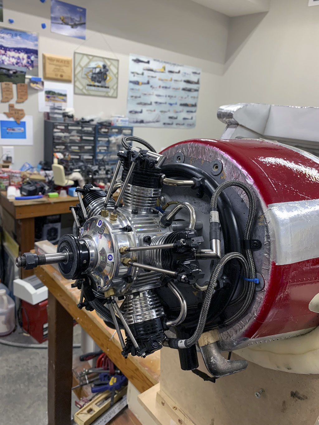
- UMS 5-75 radial engine offers great performance for the 195 airframe
Anyway, as do all Mr. Hostetler's designs, his Cessna 195 soon developed a reputation for flying great (a reputation, which persists to this day). Moreover, according to Ray and Elaine (who continue the Hostetler's Plans business since his passing), these are an immensely popular set of plans. Especially amongst discerning builders wanting something to distinguish their craftsmanship from the run of the mill ARFs found at most flying fields.
Note; I swiped this next photo off their plans-page for the Cessna 195 . . . the one I linked to above. Moreover, I'm using it here for pretty much the same reason they use it on their website, to stir the juices!
Like isn't this a stunning example of the breed? Just look at how that bright red and maroon color scheme glistens in the sun!
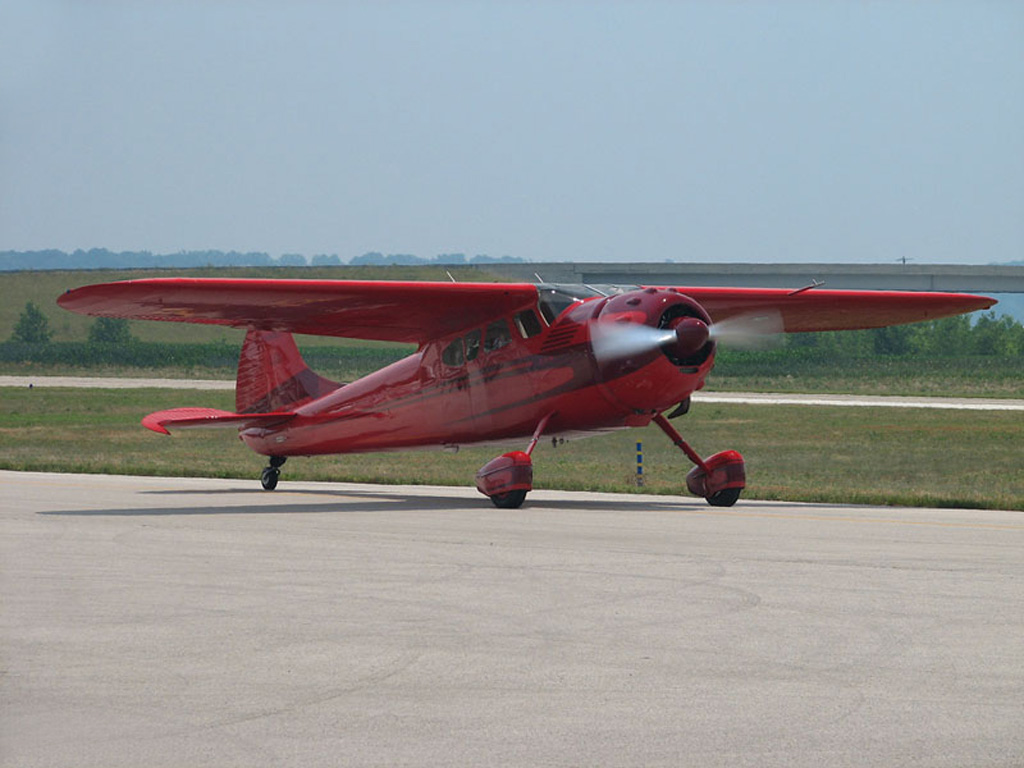
- Up elevator to firmly plant the tail wheel
So circling back to the full-scale aircraft, while the big Jacobs R-755 radial up front makes the 195 seem like it belongs in the golden age of aviation (defined as between the end of WWI and the beginning of WWII), Cessna actually produced the 195 after the end of WWII (between 1947 and 1954). The unfortunate thing for Cessna is this; with the 195 they brought a knife to a gunfight! Let me explain.
Birdwalk
In offering up the 195 to the postwar market at the same time as the Harmon designed 4-passenger Beechcraft Bonanza, it was inevitable they'd lose. Why? Since I own the Bonanza in this next photo, and because as it happens I've flown a Cessna 195 as well as a Model 17 Staggerwing, kindly allow me to add a little insight.
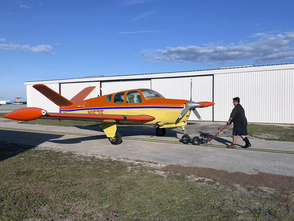
- Sporting bright colors, this aircraft isn't lost in the crowd
In a nutshell, money. Both the Model 17 and 35 fly with lighter, more balanced controls, but the Bonanza's fuel economy is a lot better than either. To go as fast as the Cessna 195 or Beechcraft 17, while they're burning 15gph I can pull back to 11gph. Add to it, most radials use a couple quarts of oil per hour, call it a gallon for a flight to Tallahassee and back. Meanwhile, my Bonanza consumes one quart in 50 hours so this maths out to as making 25 round trips per quart of oil vs 25 gallons of oil. Anyway, when you put pencil to paper, operating costs are always a big part of the conversation.
But it's not just operating costs. We're talking about like-for-like aircraft pricing of $7345 for the Bonanza vs $12,750 for the Cessna 195 (using 1947 dollars). An extra $5000 in acquisition cost got you something slower which consumes more fuel and oil. This goes a long way toward explaining why Beechcraft built 785 of the Staggerwing during its production run, and Cessna built 1180 of the 190 and 195 combined, while Beechcraft went on to build more than 18,000 Bonanza.
Anyway, both the Bonanza and the 195 were all-aluminum aircraft riveted together from sheet metal, plus stampings (like for ailerons and elevators). That, versus old school welded 4130 Chromoly tubing, wood, and fabric of the Staggerwing. But the svelte Bonanza fuselage and retractable landing gear delivered better aerodynamic performance than the fixed gear Cessna.
These were enough of an advantage that a 470ci 6-cylinder boxer configuration engine could outrun the more powerful and significantly more thirsty radial engine, which at 757ci displaced 60% more cubes! That's rather a lot of added displacement for no increase in performance. And being both lighter and more simple, the boxer cost less to buy than the old-school radial engine.
Costing less, and consuming less, all while offering greater speed and similar payload made for a no-brainer decision-wise, agreed? Anyway, the Bonanza promptly ate the 195's lunch because like most business decisions, money pretty much trumps everything.
Birdwalk, part II
If you'll kindly allow me to go a bit further with this birdwalk, because both had a focus on the same business-owning buyer, the release of the Bonanza quickly forced Cessna back to the drawing board. So what took shape emerged quickly (two years later in 1949). Talking of a Cessna prototype named X210. This tail dragger uses a variation of the same fuselage, but with a new face due to ditching the 42-inch diameter Jacobs in favor of a boxer-configuration Continental. It also had tubular versus flat landing gear legs.
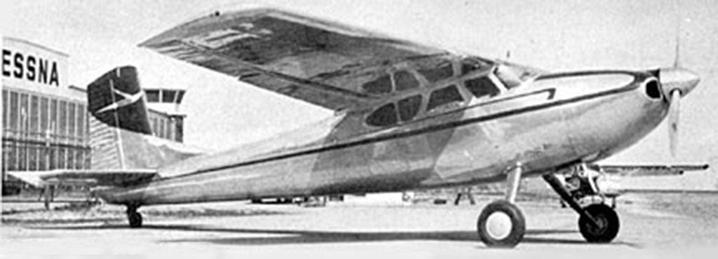
- Cocky vertical stab and proud nose high attitude
But the big difference was wing-wise, where things were distinctively different because they ditched the expensive and time consuming to manufacture elliptical wing panels (think Spitfire-esque). In their place, the now familiar constant cord center section, plus tapered outboard panels took their place.
Moreover, it was equipped with trailing edge flaps. Like those on the now famous 150, 170, and 180 (the predecessors of 152, 172, and 182) use. So the gorgeous elliptical no-dihedral wings with split flaps went away in favor of far less costly to build wing equipped with squared off tips.
That, and the less expensive, simpler to maintain, lower oil consumption, 6-cylinder boxer configuration engine replaced the radial resulting in more cost savings. The installation of which, resulted in the fuselage cleaving the air more cleanly. Honestly, I find the X210 to also be a pretty airplane. Especially with that jaunty vertical stab . . . as if announcing itself to everybody!
Note; the new prototype came to naught. Why? The Korean conflict. Basically, Cessna took the immediate government money of building Bird Dogs for the military over continued investment in a new flagship for the civilian side of the business. After all, Clyde Cessna & Company knew rule #1 for any business is . . . cash flow is king.
Point being, when they finally took another swing at the pitch (executive transport), it resulted in a similar name, 210, but the Centurion was an all new fuselage and retracting gear with seats for 6. FWIW, this forced Beechcraft into making the 19-in stretch Bonanza named A-36 (to also tote six butts aloft). This, because competition is the nature of the free market!
Anyway, and by pretty much any objective measure, the curvaceous Art Deco-like 195 is a very sexy looking aircraft!
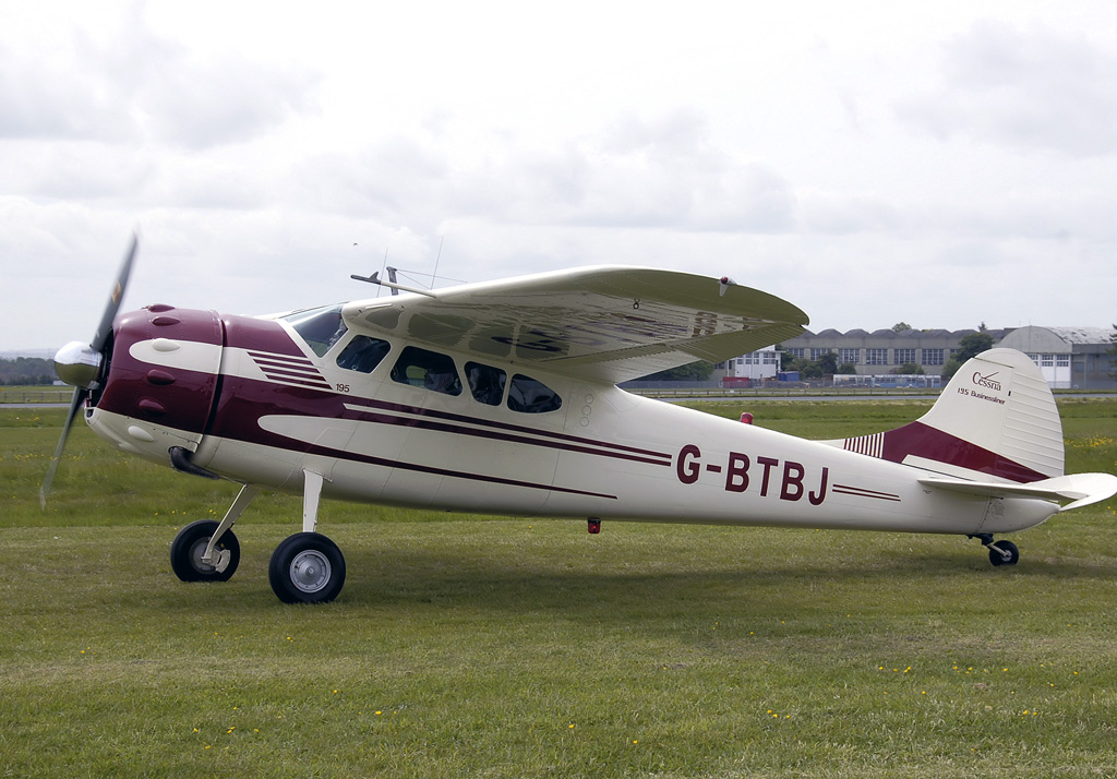
- Eyeball disk brake calipers mounted aft of the axle
Birdwalk, part III
So guiding him toward a good set of servos was easy. However, this was aided by the fact I happen to have experience with a similar size Cessna 195. However, mine's an ARF once offered by ECOM RC (long defunct). And while mine is slightly smaller at 107-inch vs 108.5-inches, I nevertheless felt perfectly comfortable recommending the same servos.
Note; my model is powered by the venerable magneto equipped Zenoah G-45.
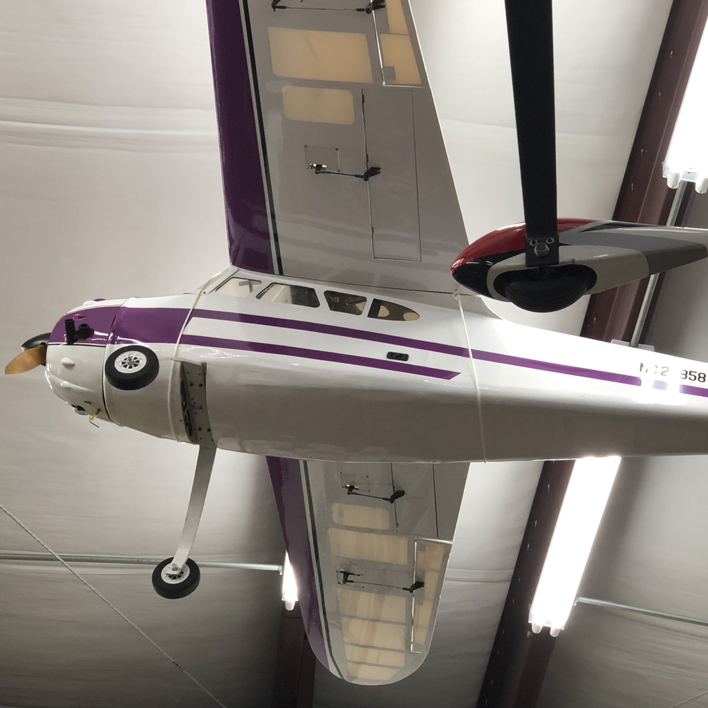
- Eyeball the split flaps of the 107-in wingspan ECOM RC version of the Cessna 195
Anyway, Matt and I said our goodbyes and signed off (resulting in one of my quickest phone calls ever). We had in mind a plan of sharing photos - the ones, which follow. To be honest, this is the end of the story with almost everybody. Like they say they'll take pictures but somewhere along the way, they forget. But as it turns out, Matt's one of those do what I say kind of guys, So he was totally serious about taking the photos and sharing them (as serious as he was about the build, itself).
So imagine my delight when the photos begin rolling in. Loads of them. So I quickly organize a directory for the model, with subdirectories for wings, stabs, etc. to keep track. And now, with a butt load of photos, and the ball's in my court. Saying the presentation of photos is not quite a drunkard's walk through them, there's actually a plan! Anyway, first up, the stabs!
We'll begin the with framing up the stabs, then go to the wings. This, because it's handy having both stabs and wing panels when building the fuselage. But then after the model is framed up and ready to cover, we're going to circle back around to stabs, wing panels, and fuselage once again. This is when we get into the detailing. But first up, the stabs.
Stabs
The job of building most models often begins with stabilizer components; the horizontal and vertical stabilizers along with elevators and rudder. Plus trim tabs.
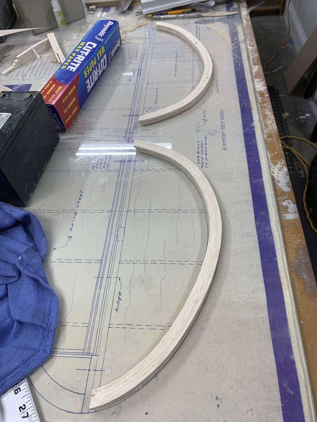
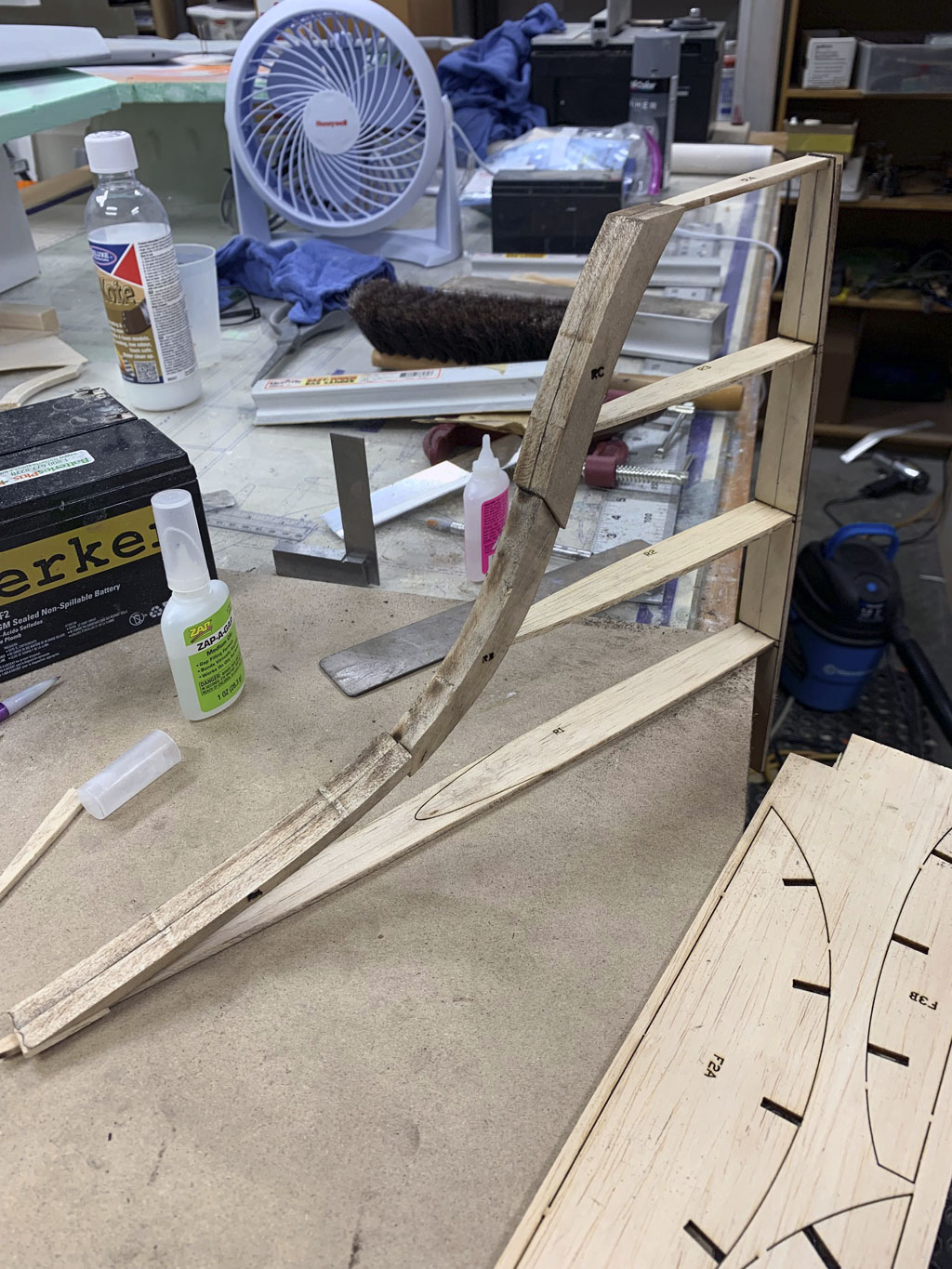
With all the gorgeous elliptical shapes, laminating strips of thin balsa is often how leading and trailing edges are typically made. So these elevator trailing edges are already dry and formed into shape. They've been removed and are ready to be dry fit for trimming before gluing into place.
Note: wax paper is what's used to protect plans because glue won't stick. and the battery is being used for its weight, e.g. to hold things down, and/or flat.
Laminating
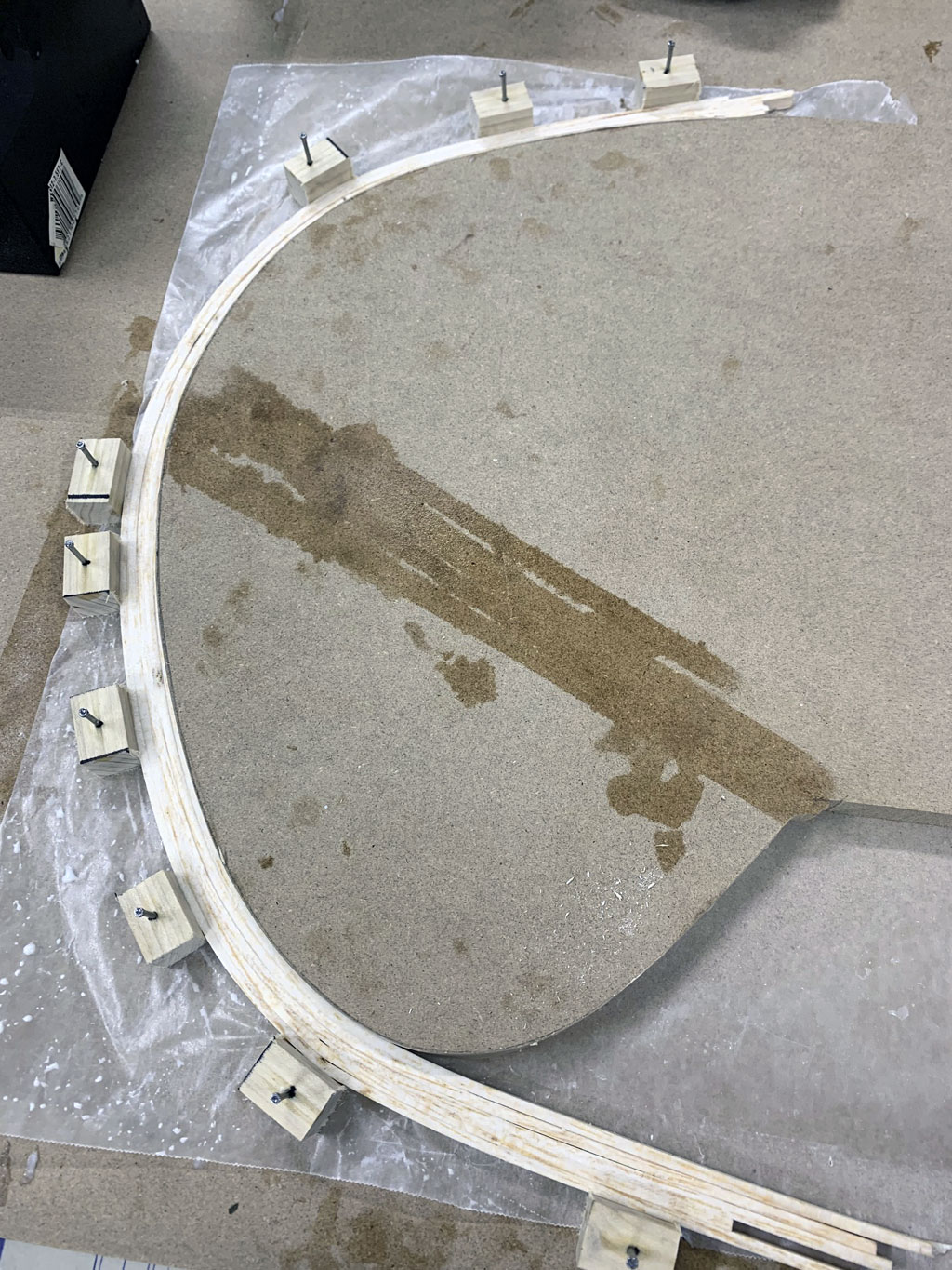
So how this curved trailing edge shape is accomplished . . . it uses a form! This one is particle board, but Masonite, plywood, or pretty much anything will serve to do the job. All it needs to be is thick enough and sturdy enough to form wet strips of balsa to shape.
Basically, the wood strips are soaked in water, sometimes with a tiny bit of ammonia added to make them more flexible. They are pinned in place using small wood blocks nailed into the workplace surface, and allowed to dry. When the bend is not too sharp, sometimes the moisture of the adhesive alone is enough to let them make the bend so they're pinned in place dry instead of being wet. Wet works beautifully, it just takes longer for the assembly to dry, usually overnight is long enough.
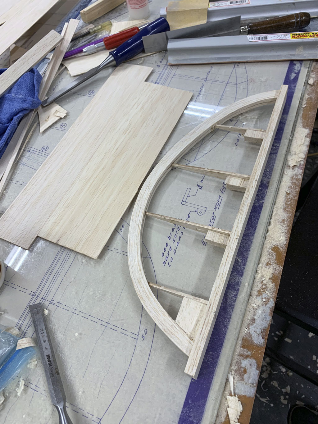
Later, the curved pieces are cut to the approximate dimension and glued up to ribs and leading edge before being sanded to final shape. Also, eyeball how in this next photo, Matt added blocking as reinforcement. The idea is solid wood will accept hinges more securely than just the leading edge of the elevator surfaces.
He also blocked where the control horn wire will be epoxied in place.
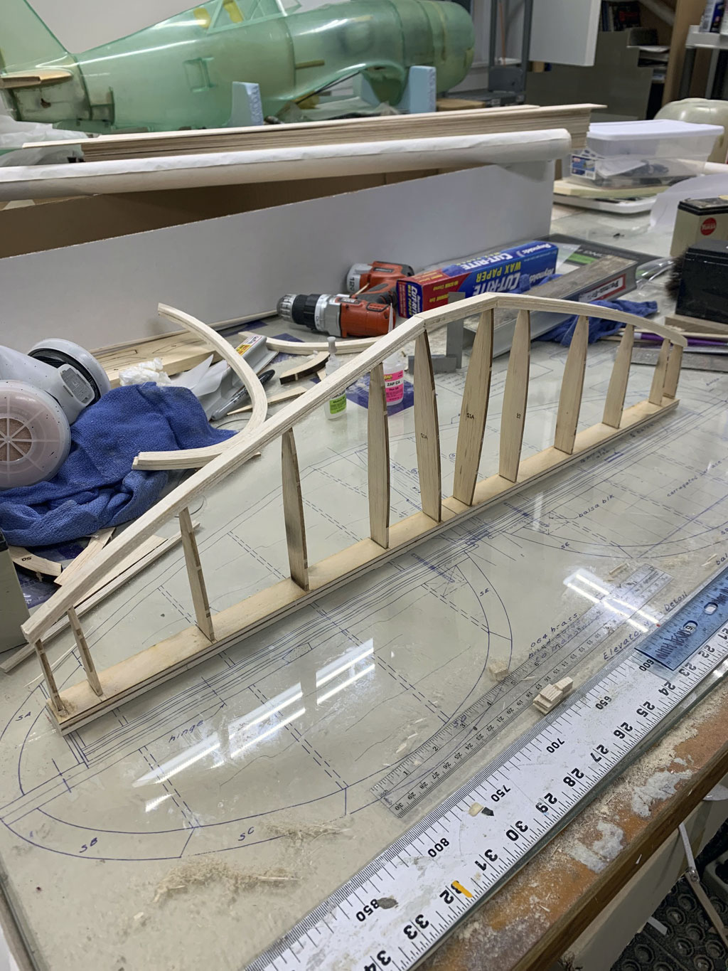
So in this next photo the horizontal stab is framed up. The two middle ribs are not crooked, that's the eye being fooled by the 2D photo. What's really going on is the two ribs are parallel to the tapered shape of the aft fuselage. Also, eyeball the razorback fuselage in the background, Matt's a builder!
Now in this photo we have the vertical stab framed up. And if you look off to the side, you'll see bits of fuselage components, which have been laser cut. As I mentioned earlier, Matt had a kit cut by National Balsa who offer laser cutting from Hostetler's Plans, as well as others . . even your plans if you have a file. Pretty sweet, eh?
By the way, this, as compared to old-school plans building where you photocopied or laser print the appropriate part of the plan (ink jet doesn't work). So be it ribs or formers, you invert the print the paper with the part printed on it and ironed it down to the wood, which transfers some of the toner from paper to wood to create cut-lines.
Anyway, this business of buying the plans and wood already laser cut is better, in my opinion.
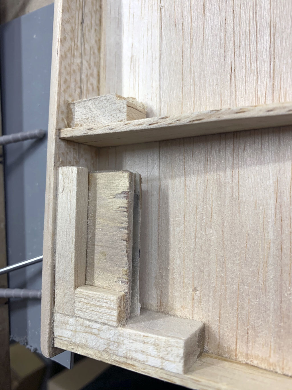
Blocking - RDS pocket
So in this next photo we're getting a good look at the blocking and structure for the rudder's rotary drive system. It's important the wood for this be hard, aircraft ply is good. Some will laminate Formica to the interior surface. Or metal. We've seen bearings used to minimize friction. So there's no one right way to go about it . . . and this is what modeling is about!
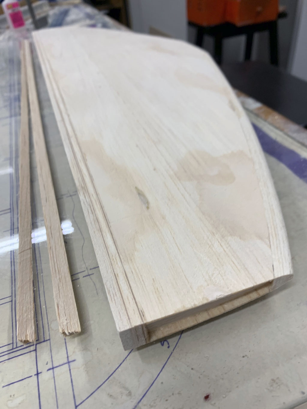
In this next photo, the stab's been sanded to shape per the plans (meaning you look at the side view and sand away everything that doesn't look like part of the stab profile). Anyway, after matching the leading and trailing edges to the shape of the ribs, the two surfaces (top and bottom) have been sheeted with balsa. This, because the full scale used sheet aluminum instead of open structure and fabric to form the flying surface. it will form the foundation for the application of Flite-Metal. But there are a few steps before getting there.
Note; the ends of the stab haven't yet been trimmed and capped. Anyway, one stab down, four to go! Five if you count the trim tab.
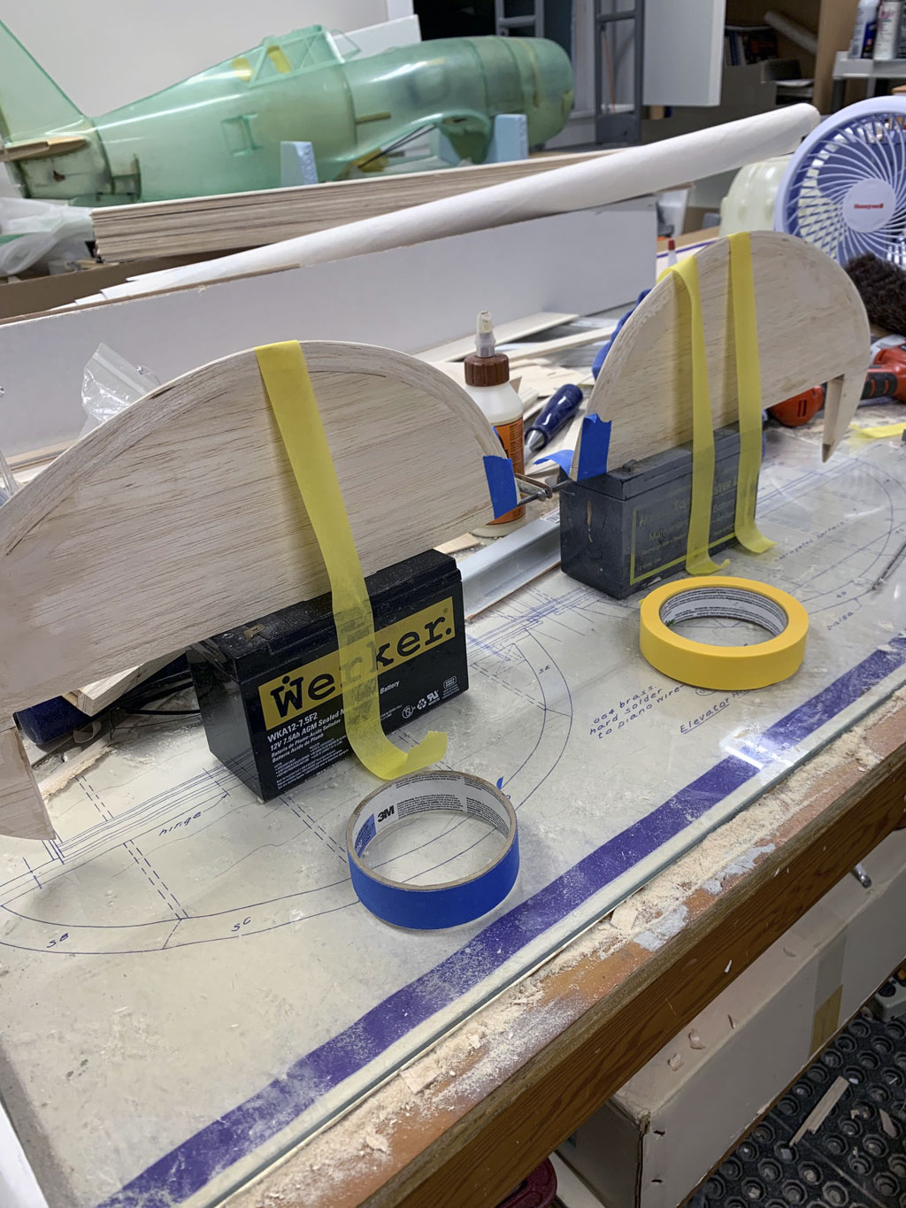
So in this next photo the two elevator halves are sheeted and sanded to shape. The last step shows them being joined with a steel wire epoxied into the predrilled wood blocks.
The purpose of this is to ensure perfect alignment between the halves. Why do this? So they operate as one control surface with a single servo but adding up elevator doesn't see one being at a slightly different angle meaning up elevator for a loop makes the model wander off course.
Note; it's my opinion joining the two surfaces this way is a mistake. Why?
Well, this is how it was done back in the day because the concept of redundant servos hadn't become widespread. Since most pilots had a 5 or 7 channel radio and servos were expensive, this is how it was done, a joiner wire. However, the advent of transmitters with 9-18 channels, some with even more, this led to using a dedicated servo to each control surface.
Saying this isn't me pitching the sale of an extra servo, it's me saying only God is perfect. Remember, the elevator servo is the only one where it going teats up almost to 100% certainty means crashing. Yes, we make fine quality servos - but - anything can fail.
So because I believe in my soul the words of Lieutenant-General Baden-Powell in the Boy Scout's handbook . . . be prepared, then because I also feel the best plan is to have a plan in advance of what to do, then once I learned to use one servo per control surface I never forgot. After all, the way I figure it, half an elevator surface beats zero control surface in the event of servo failure. Heads up.
Glassing
Anyway, in this next photo, Matt has covered one side of the elevators with lightweight glass cloth and resin. He has them sitting on a pair of cans so that the edge of cloth and resin can hang straight down uninterrupted by a work surface.
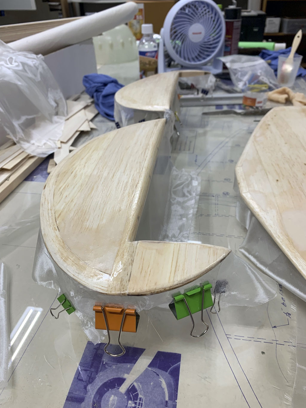
So the vertical fin and rudder are built and covered the same way. However, there's a twist. Instead of the rudder servo being up front with a pushrod, e.g. near the CG of the aircraft, it's being embedded into the vertical fin. Matt does this with ailerons and flaps, also.
Servo pocket
Here's a photo of the vertical fin structure with the pocket to contain the servo. This works by virtue of the wire having a 45° bend and as it rotates back and forth, the end of the wire rubs on a hard surface and essentially flicks the control surface up and down. Of course, this requires prior planning, e.g. by building in the structure forming a pocket.
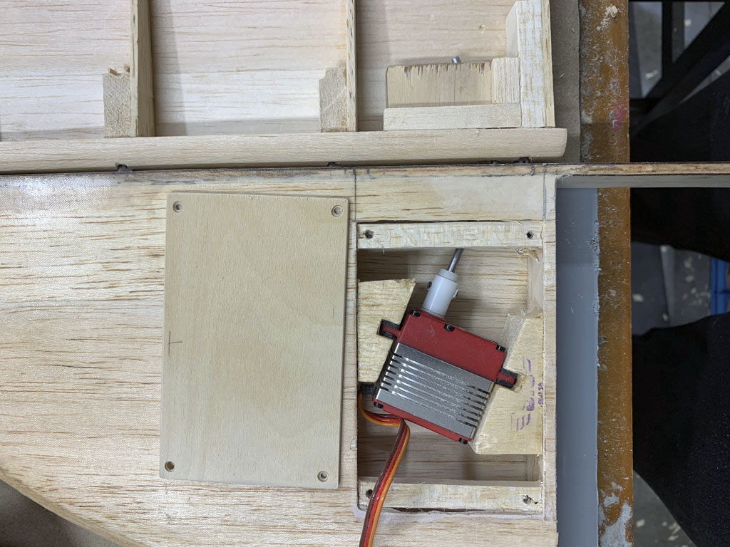
How rotary drives function
So for a better explanation, I went online and found a 3-minute video. It was published around 2011, or just a few years after YouTube came into existence. However the fact it's old doesn't negate the value because this guy went to a lot of trouble to show how this works. It's my opinion the video is brilliant, else I don't bother to share it.
Me? I gave him a thumbs up and subscribed to his channel because everybody should be rewarded for their work!
Wing panels
Framing up the wing panels is easy enough because the laser cutter (National Balsa) thoughtfully added tabs. This, so you can build it flat on the workbench. After gluing in the spar, plus leading and trailing edges, along with sheeting, the whole thing is sufficiently rigid to unpin from the work surface and flip over to install the other spar and sheeting.
It's a nifty method for building wings I'm not sure I would have been bright enough to come up with on my own. Before I saw this, I either used a jig with steel rods, or shimmed the leading and trialing edges into place before adding ribs and spars. Tabs are better!
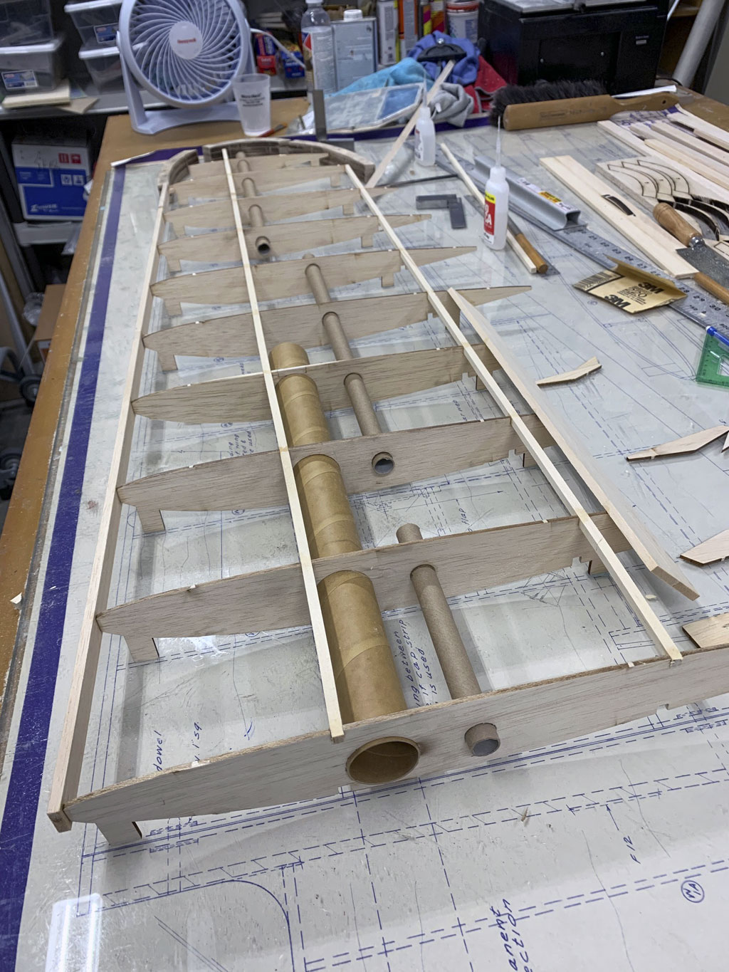
Now in this photo we get a better look at the wingtips. These are built up of several layers and instead of being bent to forms like the rudder and elevator trailing edges, they're comprised of three pieces individually cut and glued together.
Note; eyeball the tools scattered about the workbench surface. These include the small square, a dust respirator, compact 12V drill in the background, plus a Zona saw (deep cut, the one with the wood handle), a file (also with a wood handle), a small triangle (green plastic), and on the left, the sheets from which the wing tips parts are cut. The blackened edge is the hallmark of laser cut parts.
Tools of the trade
There's also an aluminum straight edge and an extruded t-shape sanding block made of aluminum to which you attach sticky back sandpaper off a 2" wide roll. I know because I own a couple, also! And the eagle eyed amongst you will have spotted the round sanding bar, also made of aluminum and near the drill, another Zona saw, this one for close quarter work and not as deep a cut. Think of these as tools of the trade!
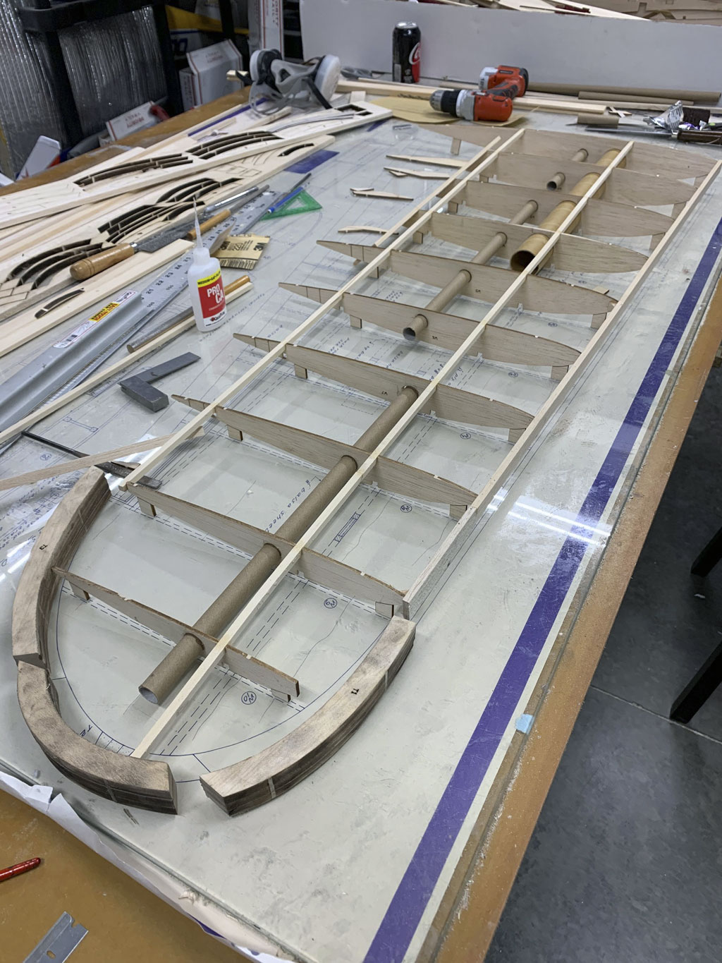
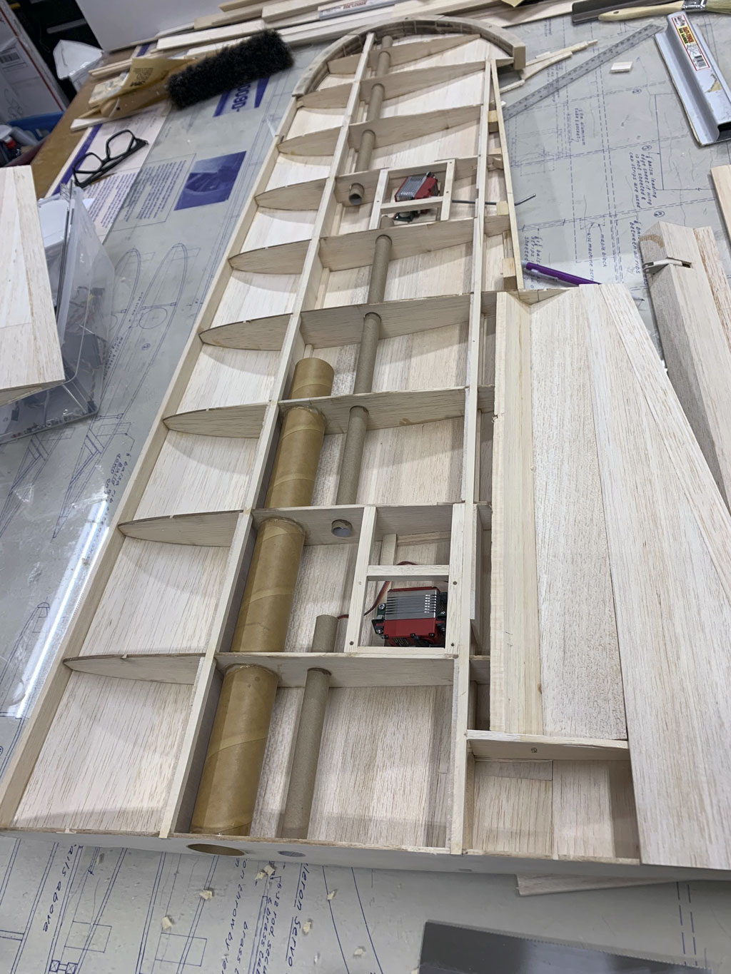
In this next photo we have the wing with some sheeting installed. The purpose of the smaller diameter cardboard tubes is for the wiring. It's how you fish through extensions for the servos plus wire for the wing tip mounted navigation lights.
Also you can see the aileron RDS poking out the trailing edge, and the aileron is cut away. More tools are visible, to include the drafting brush, a small 1" wide paint brush, and readers!
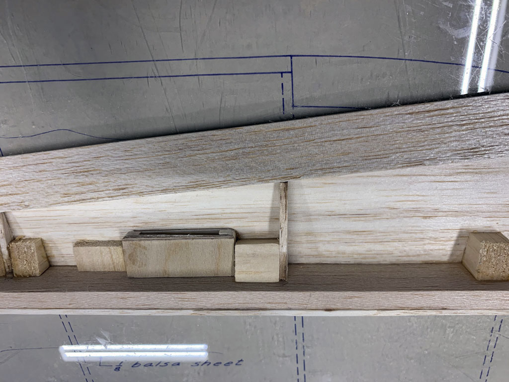
Now we get a great look at the pocket for the RDS and how it's built into the aileron. Basically, plywood forms the two hard surfaces against which, the wire wiggles up and down as it rotates back and forth to actuate the control surface.
As for the spacing between the plywood plates? That's easy, the thickness of the wire determines this!
Now in this photo we get another look at an RDS, this time a close up showing the angles required to make this work.
And now the same angle but this time showing the aileron placed in position!
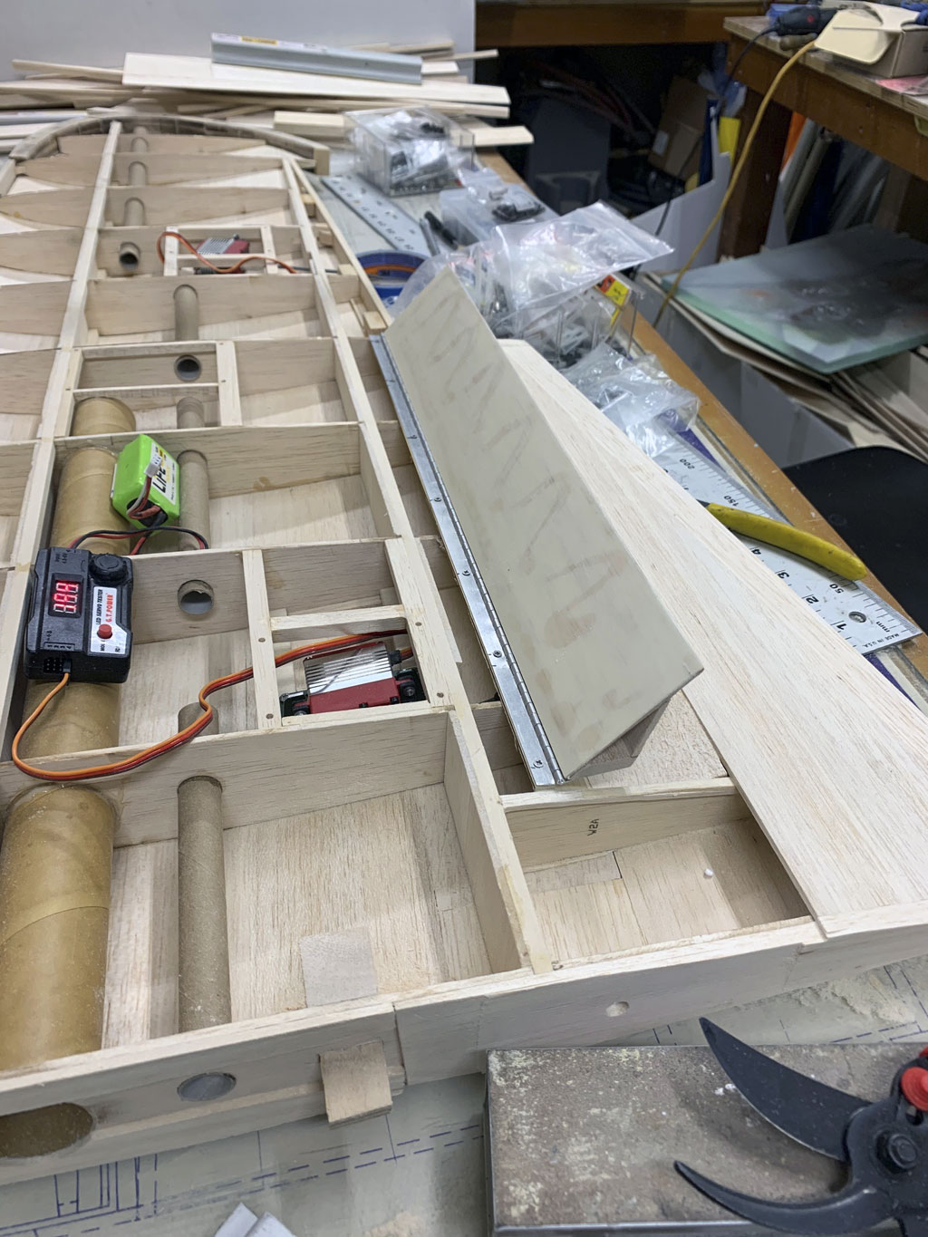
This next photo takes us to the aileron servo installation. He's using a piano hinge, and the s-shape of the thin CA is to stiffen the surface. Here we have the flap stowed away, or retracted.
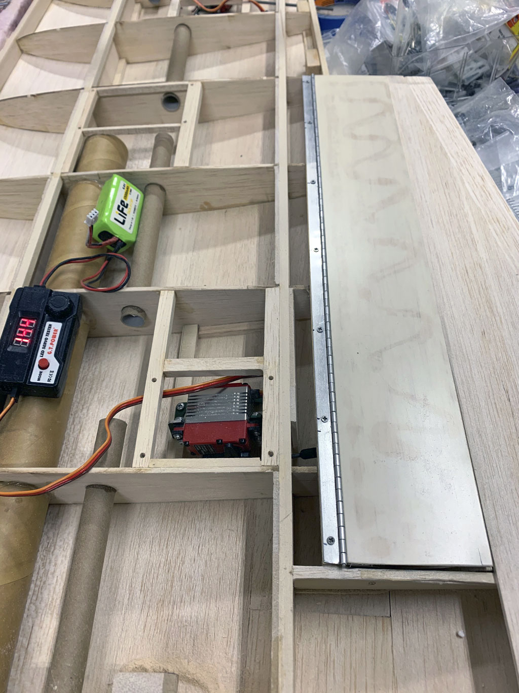
And now the same angle with the flap extended. Note how the surface is actually triangular in construction to avoid it twisting under load. So Matt's using a servo tester to actuate the surface instead of a receiver.
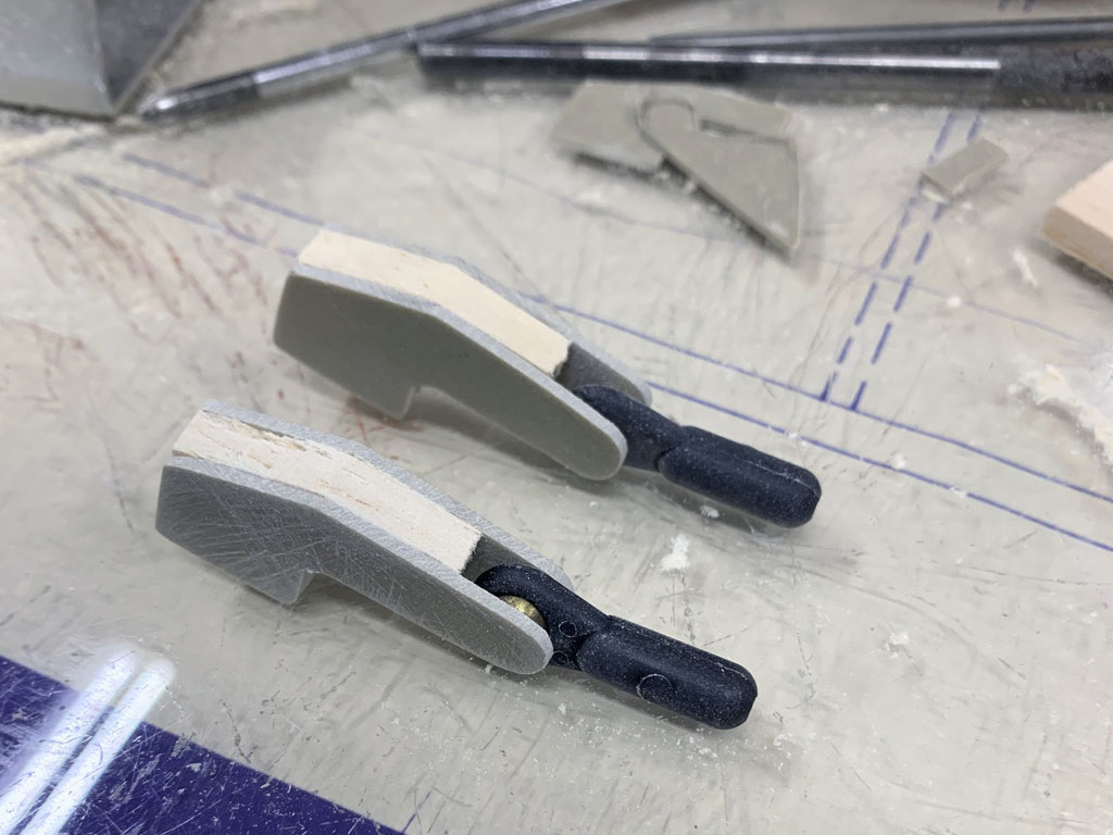
As for how he's driving the flaps, he made these up using bits of G10 and ball links. Easy peasy!
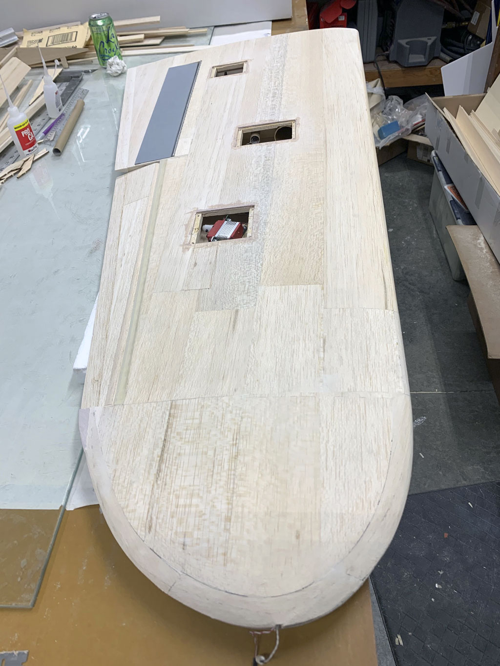
So in this photo we have the sheeted wing. Two openings are obvious, the aileron and flap servos. What about the third? Well, that's for the landing lights.
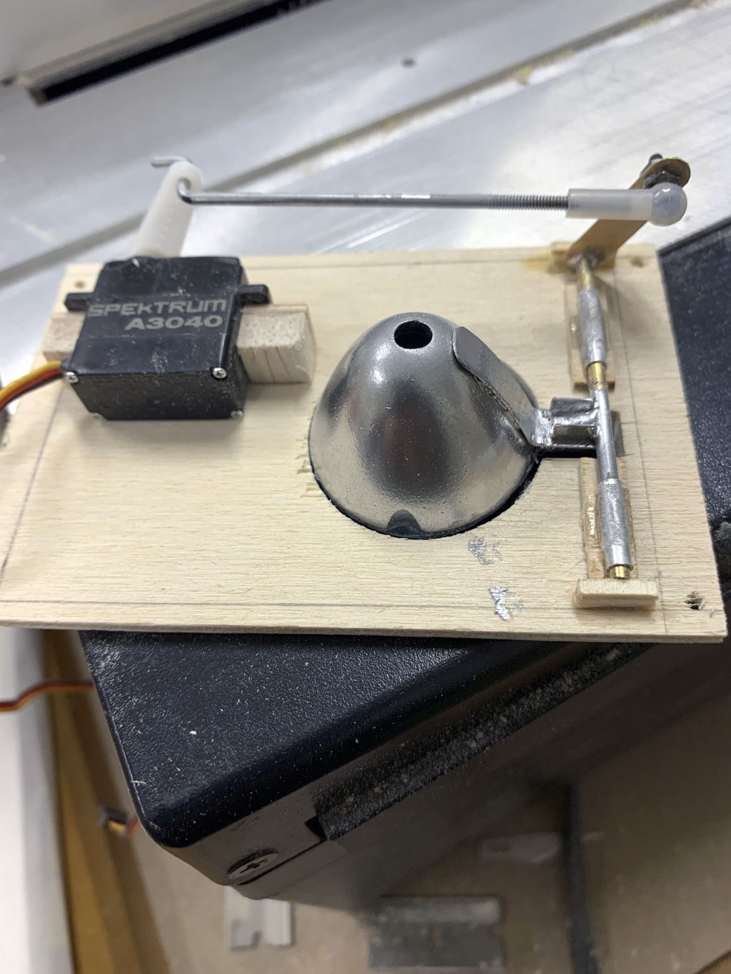
Now in this photo we see the close up of the mechanism to extend and retract the landing lights. Pretty neat, eh?
This wraps up construction of the basic wing panels. We'll circle back around to them for detailing, but up next are photos of the fuselage build sequence with details that will knock your socks off, I promise!
Fuselage
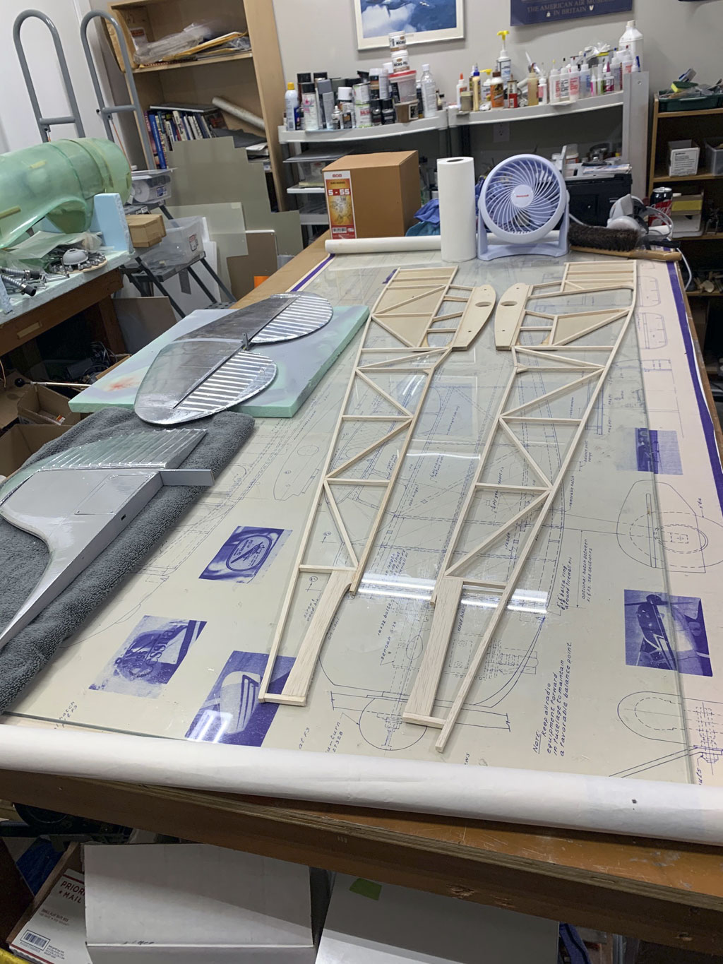
As usual, fuselage sides are built directly over the plans after first protecting them with wax paper. I've skipped some photos he shared because this one is good enough. Here we have both sides completed. The eagle eye amongst you will have noted the right side has the opening for the cabin door cut out. Maybe you're wondering how this affects strength.
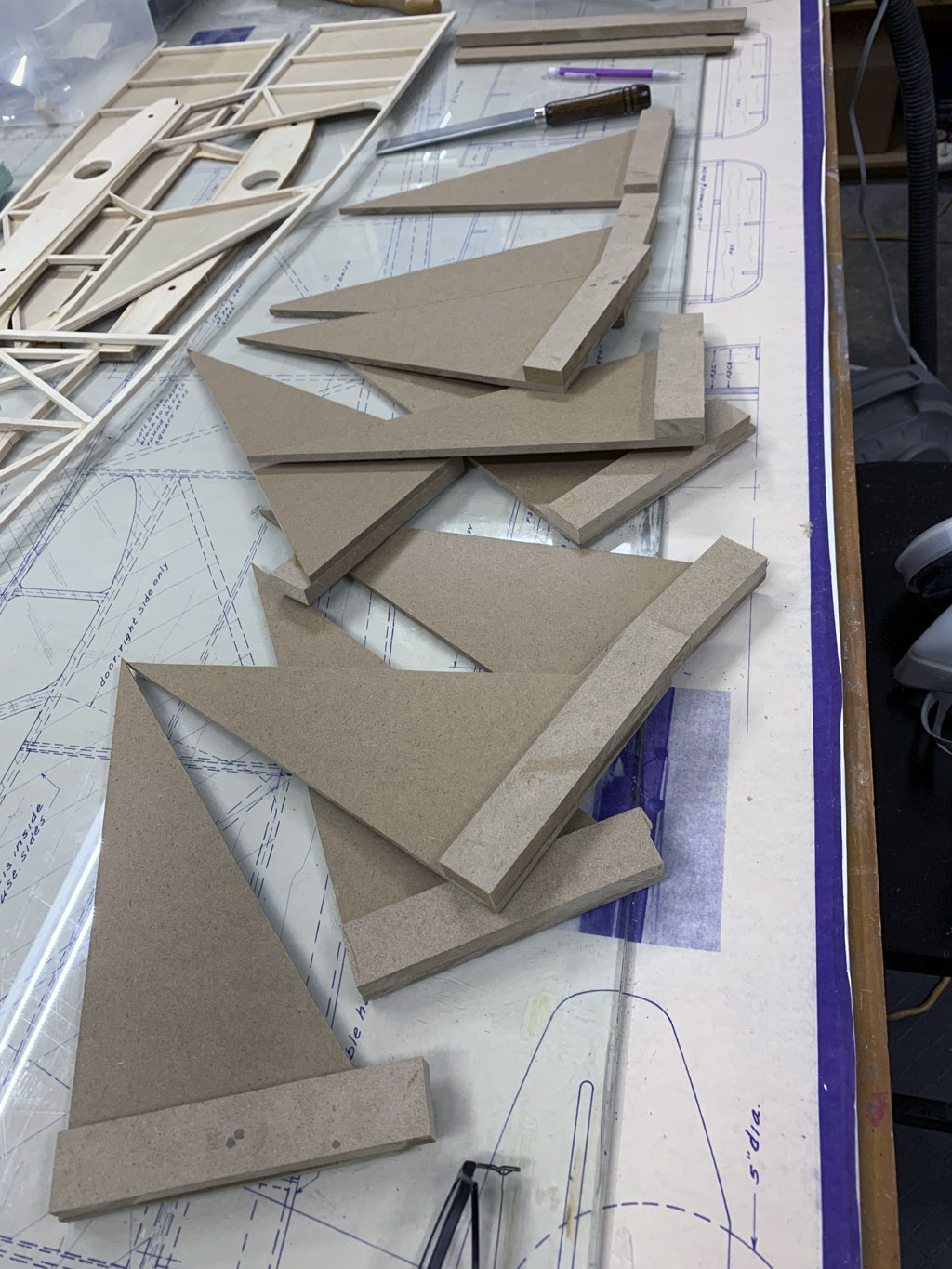
In this photo we see the building squares Matt made and which he uses to hold the sides in position.
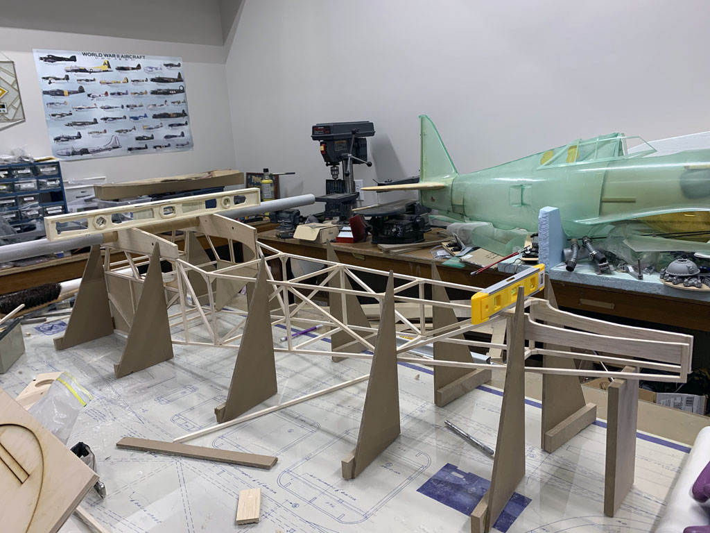
And now the framing squares deployed to align the two sides. Eyeball the use of a piece of hardwood board used to prop the tail post at the proper height.
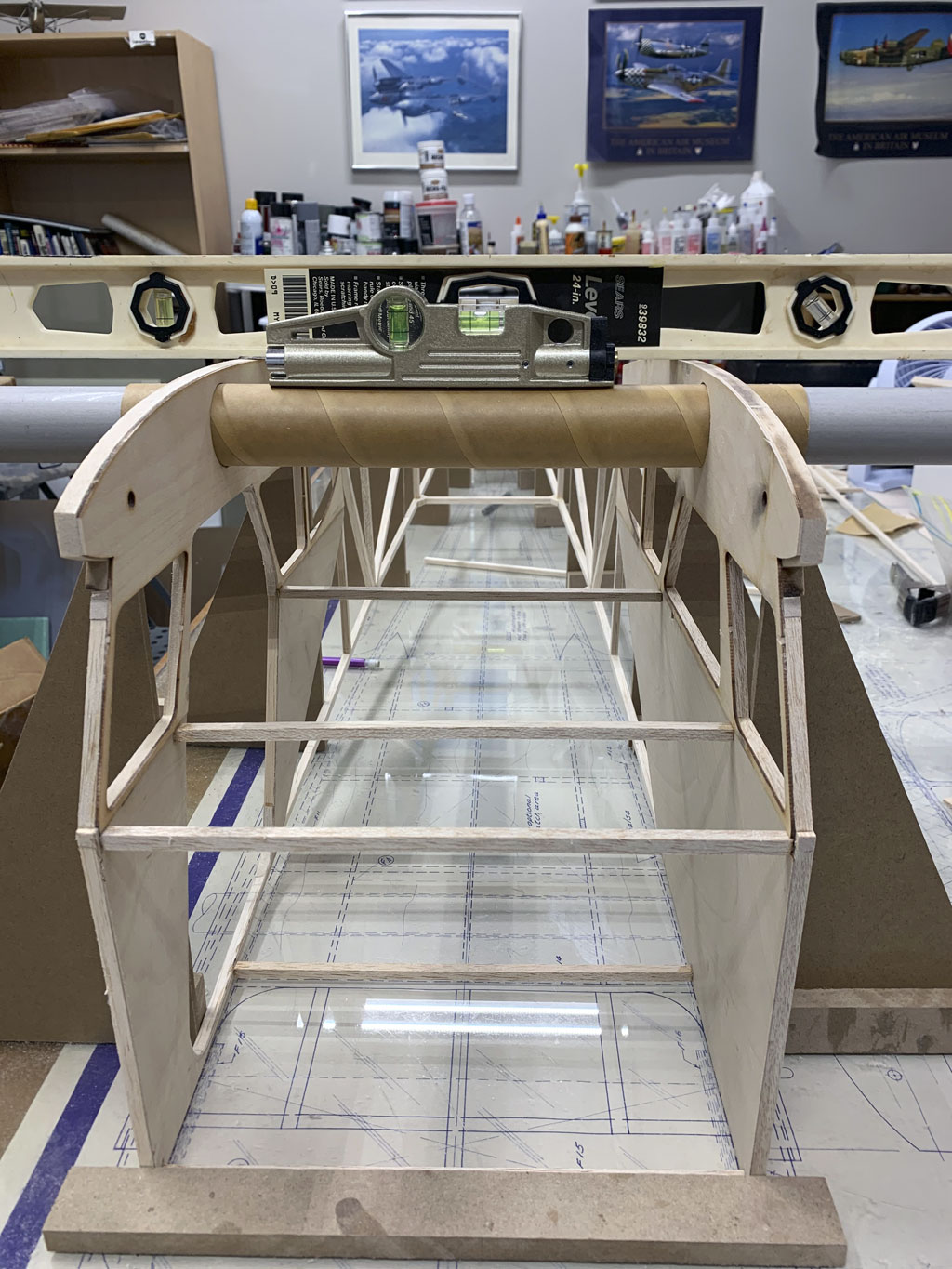
Note; the use of a three levels. There's a 24" at the upper fuselage where the wing tube goes through, and the other we can see is a smaller bullet level, which is sitting in the saddle for the horizontal stab. The third, which is hidden from view is on the wing tube itself.
Anyway, the use of these two is to ensure the upper surface of the fuselage and horizontal stabs are both parallel and 'square' to each other (and of course, level). The basic idea is you don't want to built the fuselage with the wings and stabs twisted, right?
Now we get the reverse view and see the third level, this one being set on the wing tube itself.
Note; the small block secured to the workbench surface for the forward part of the fuselage. This gives a surface against which the fuselage sides can be pressed against.
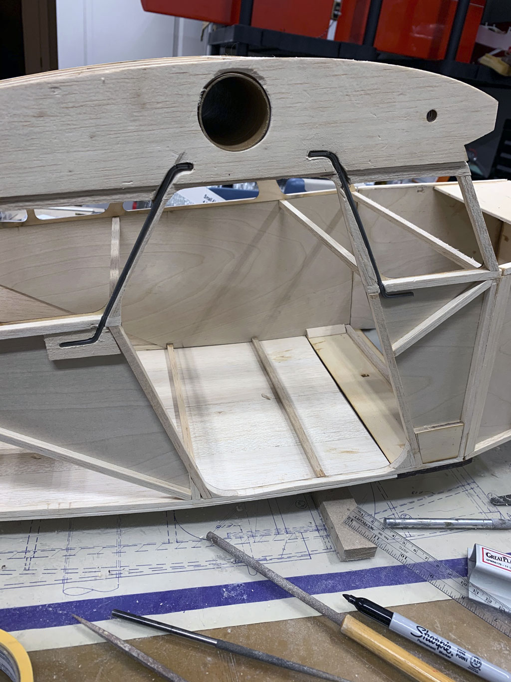
Earlier I mentioned the fuselage is weakened at the cabin door opening. In this photo you can see how he reinforces the upper part by embedding music wire using epoxy to strengthen the opening.
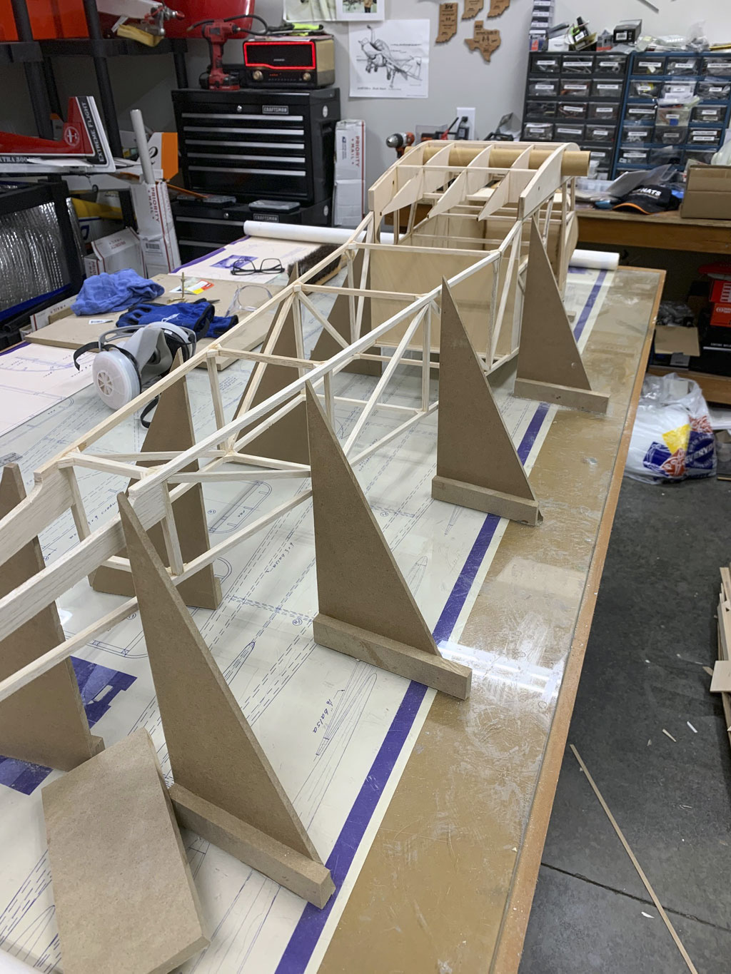
Anyway, this aft shot shows the ribs added to the wing tube central fuselage to attach the balsa sheeting. Also take note of the plywood on the inside of the cabin area.
Now let's circle around to the forward part and fitting the firewall. The blocks wedge in to hold it in place.
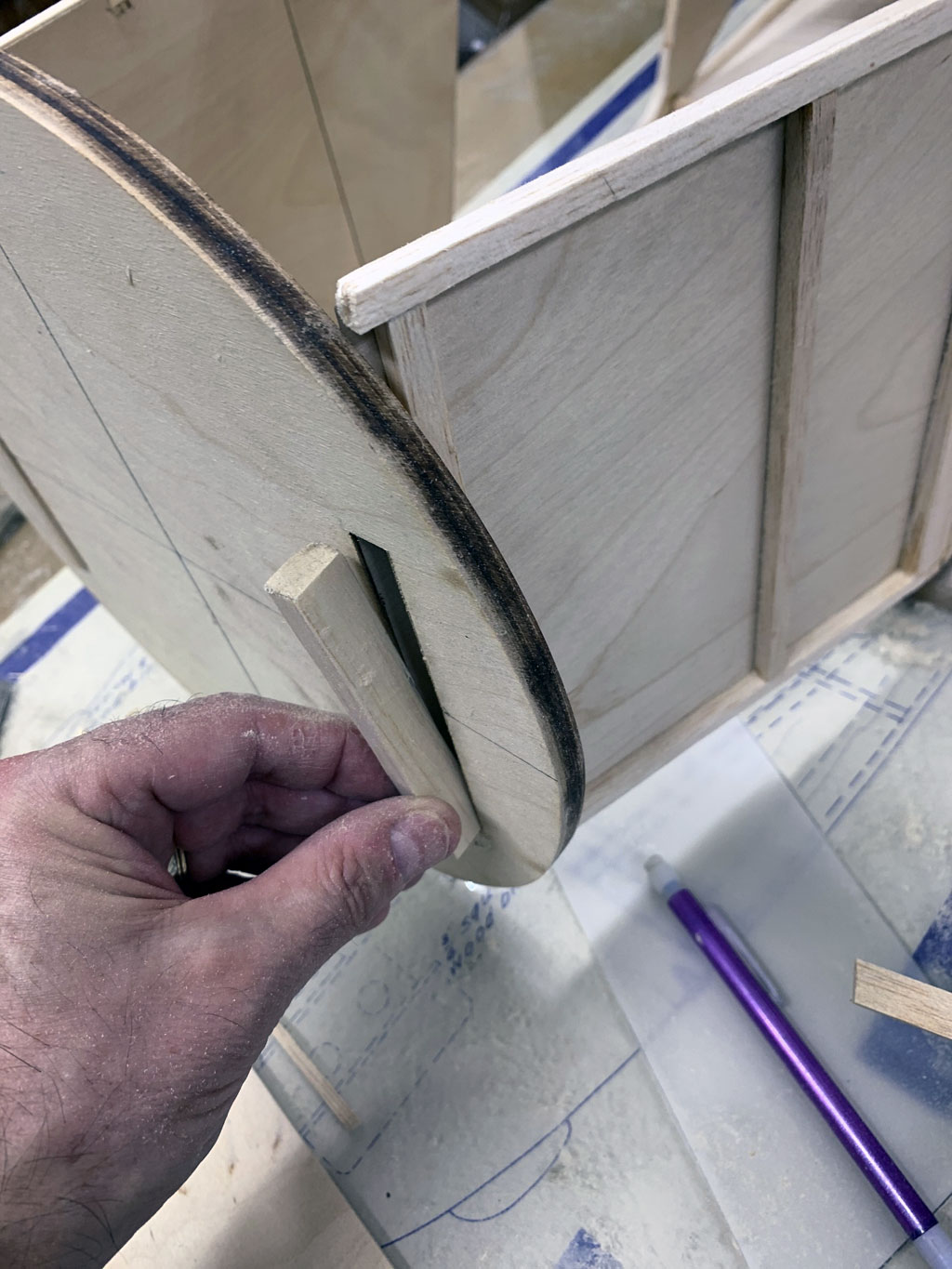
Once the firewall is epoxied in place, the fuselage is really starting to look good, isn't it?
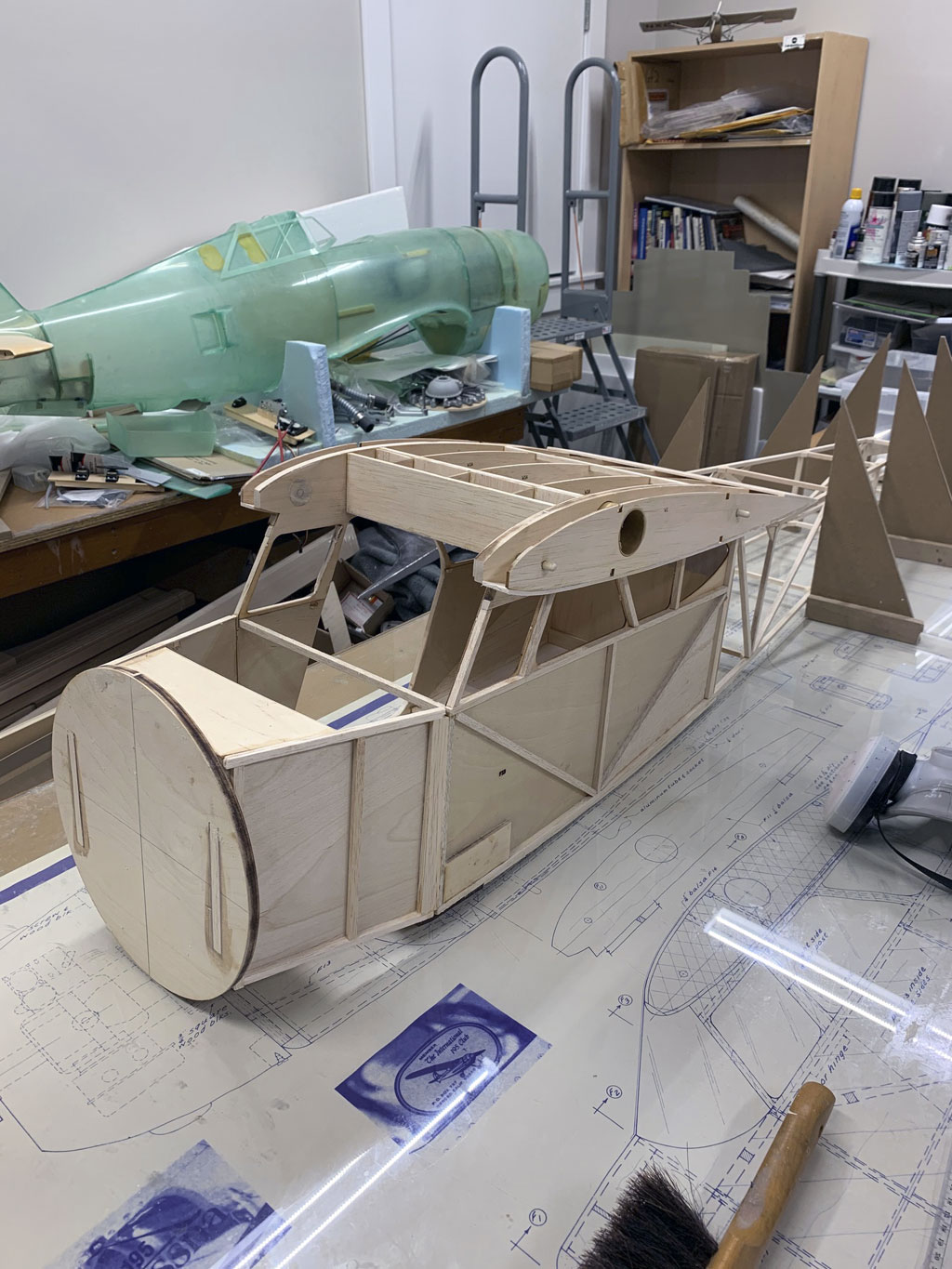
Note; alignment dowels are installed in the ribs on the fuselage for where the wing panels slide home.
Obviously, corresponding holes are in the root rib of the wing panels. Anyway, these dowels are rounded off on one end using 180-grit sandpaper and then epoxied in place. Finally, using the deep cut Zona saw, they're trimmed flush with the inner edge (flat with the rib surface) and then sanded smooth.
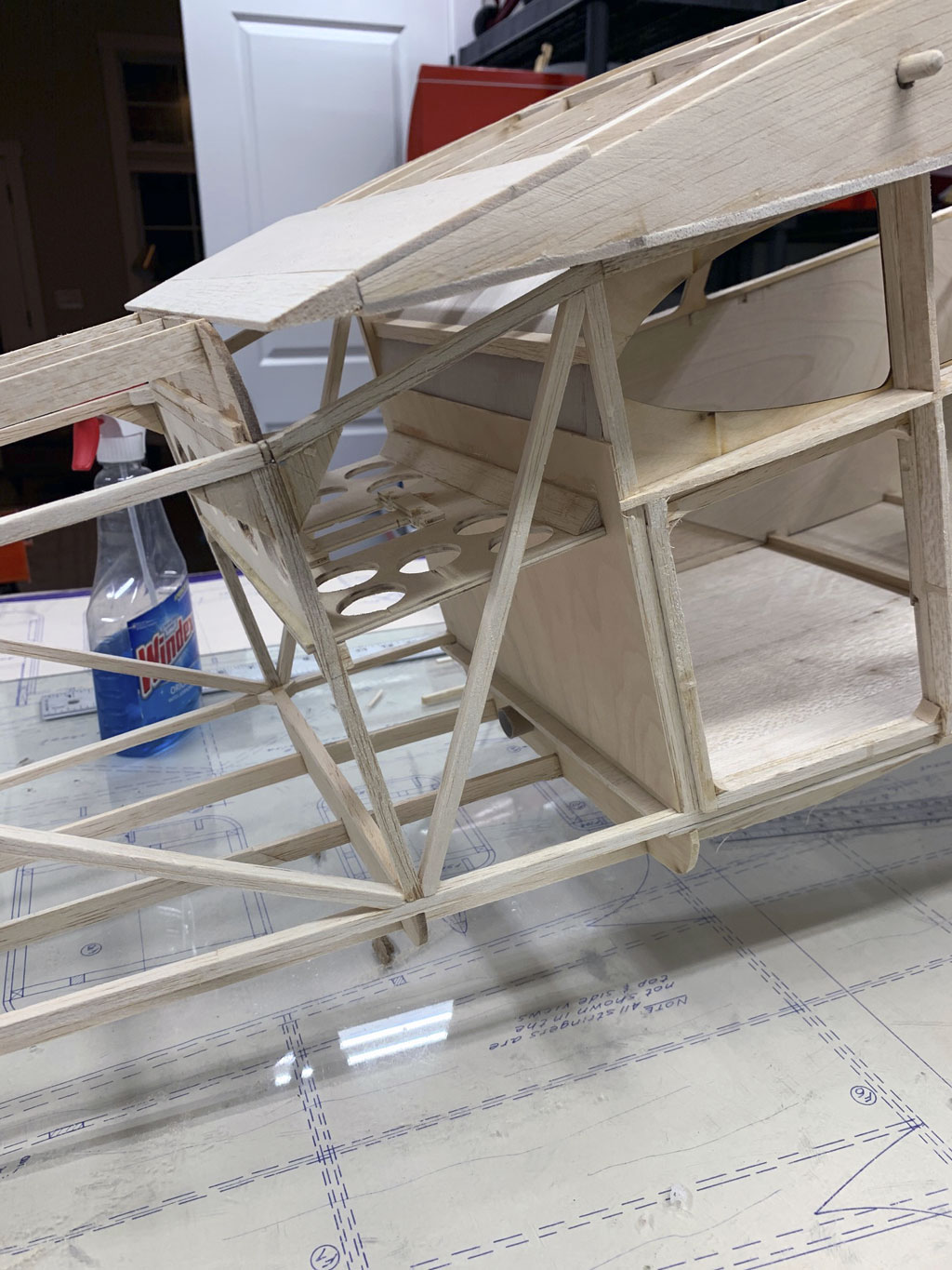
The purpose of sharing this shot is to show the plywood tray where, because the cabin is to be finished out, the servos for rudder and elevator will be mounted. This since the avionics must be hidden from casual view.
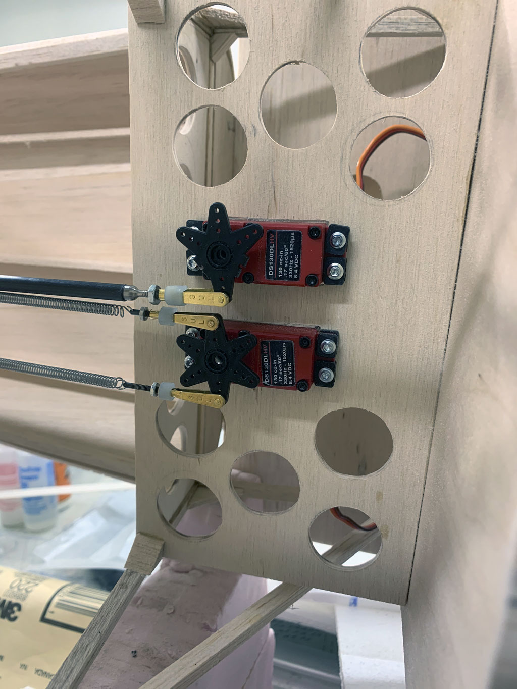
And while access is still easy, he mounted the two servos into place.
FWIW, the receiver and battery will also live on this shelf. Ditto an Aura 8 gyroscope and the avionics switch. But more about this later in the detail section. For now, just the servos.
Note; eyeball these control linkages. The carbon fiber rod is to the elevator, the springs are to wire leading to the tail wheel tiller.
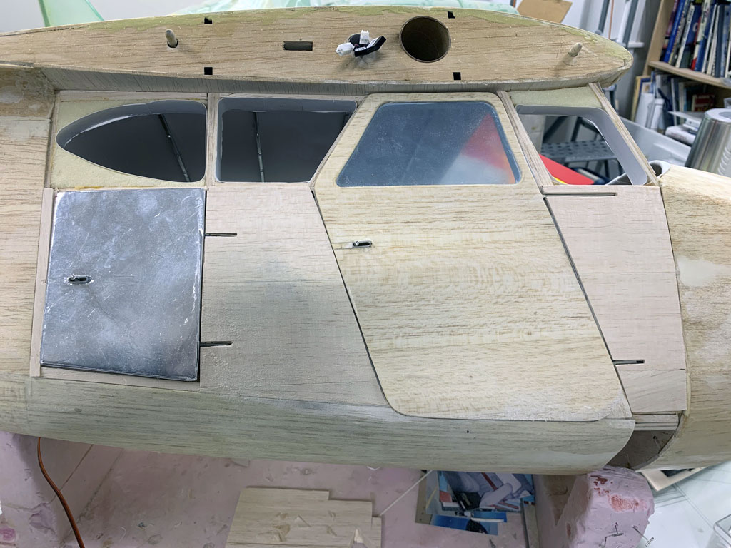
Now let's get back to the access doors for the fuselage, these being the baggage compartment and the cabin door. These are framed out in balsa and hinged. Glazing is installed in the cabin door (1/32nd Plexiglass with the blue protective sheathing still attached to preclude scratching the surface).
But because the above photo is closer to the end result, let me back up to show the hinging and begin to share details.
Note; what you want to focus on is the hinging of the aft baggage door. The cabin door is hinged the same way.
Also, eyeball what's laying on the workbench surface, the bit of plywood for the instrument panel. This because one of these projects is not completed in perfectly linear fashion. Most builders I know, me included, have several things going on at once. Matt's cut from the same cloth. Anyway, pay attention to the door latch, too. And while you're looking, yes, that's a tiny bit of filler around the rib where the leads come through. The guy's such a perfectionist he even smooths out hidden places nobody else would notice.

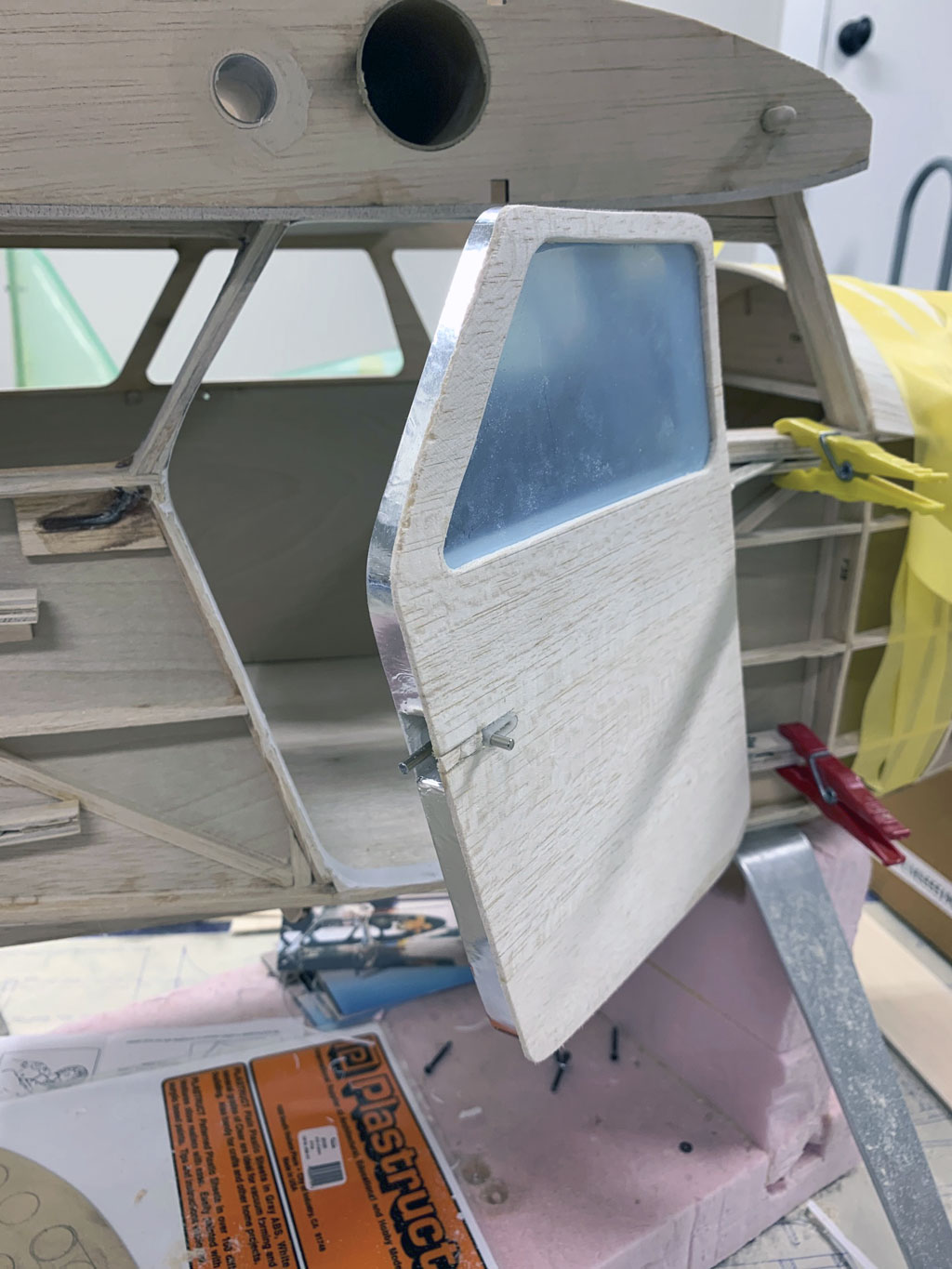
So in this photo we get the reveal and the beginning of the details we'll get to in a little bit. For example, the door skin sits flush to the fuselage but the structure is going to be finished. So note the Flite-Metal strip on the edge. Also, look at the pocket for the door latch.
Oh, and obviously he has to be able to remove the doors to work on them, hence the clothes pins. But look closely at the jaws and you'll see he's modified them. Are you beginning to understand what I meant digging for gold in the details of Matt's photos?
Note; at this stage of construction, the model is now sitting on the main gear. We'll briefly touch on that in a bit, but first, let's eyeball the inside of the cabin.
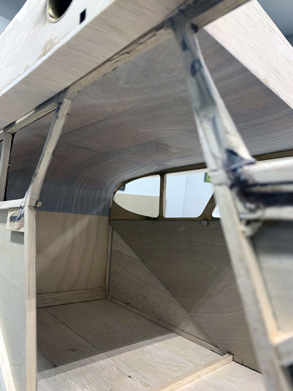
The purpose of this photo is to share what the plywood surface finishing off the cabin interior look like before it gets covered in fabric. Obviously, the door has been removed for this.
And since I'm a builder like you, I take special interest in the tight fit of the curved plywood to the fuselage sides. This guy is a true craftsman!
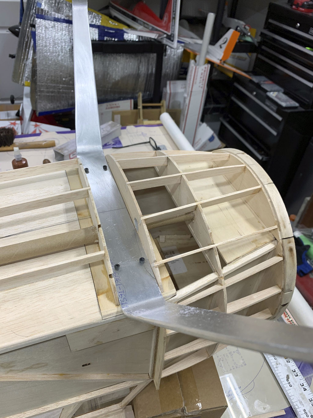
So with the fuselage inverted we get a look at the dural aluminum main gear legs installed to the bottom of the fuselage structure with Allen head bolts. But what's with the cardboard tube? Let's get a better look!
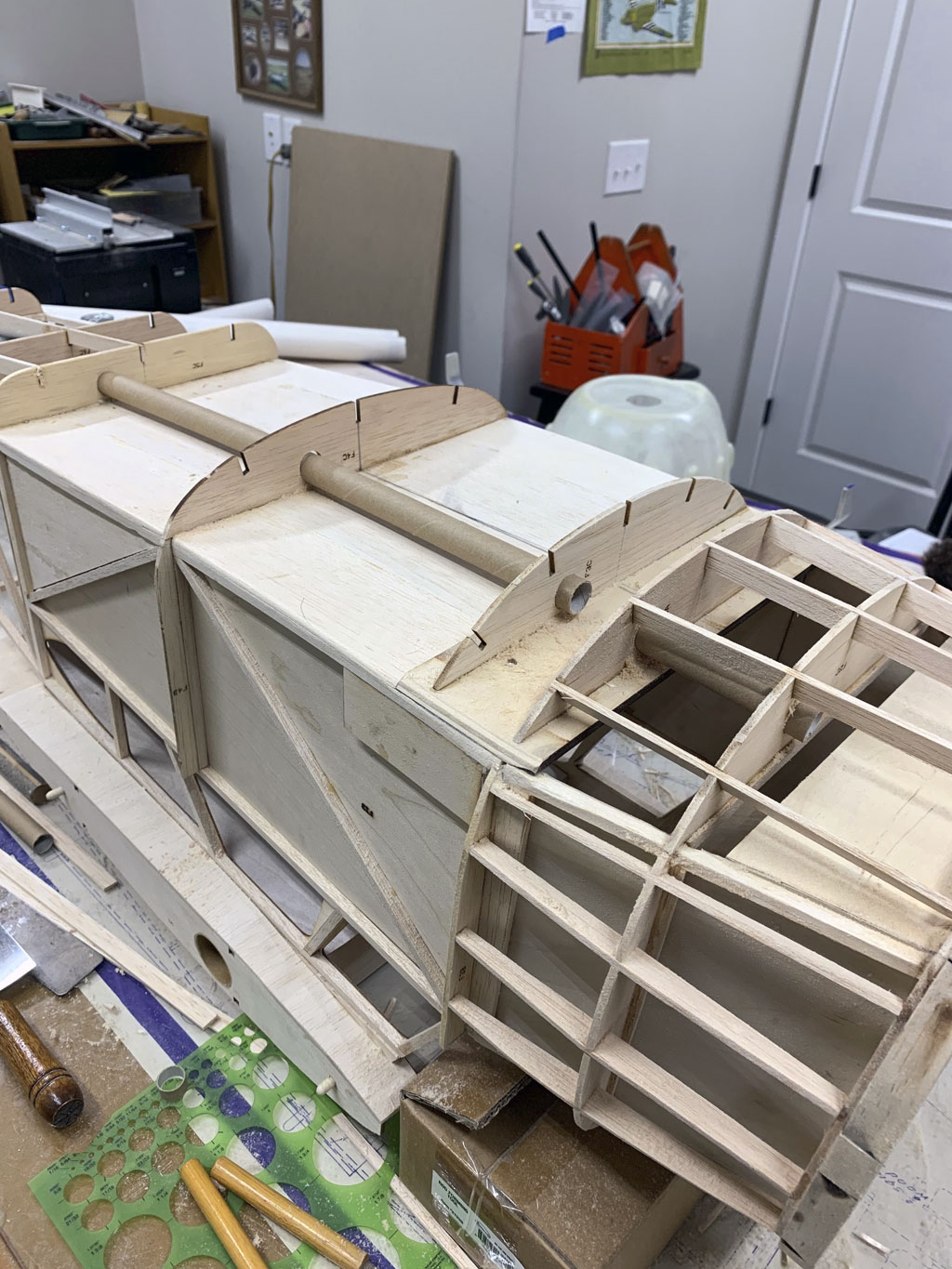
So with regard to the tubes, they are like the ones in the wing panels for routing wire leads, e.g. for the throttle servo mounted up front to the aft avionics bay where the rudder and elevator servos, plus receiver, battery, switch, etc. are mounted. Obviously, the tubes are large enough for other wiring, e.g for lighting.
The major point being, you don't want to paint yourself into a corner. Thus, a bit of prior planning avoids piss poor results (meaning tearing things out to do over again).
Note; notice the nice fiberglass cowl sitting in the background, it's by Fiberglass Specialties, more in a bit.
So in this next photo we see the fuselage beginning to be covered in balsa sheeting. If you look closely, you can also see the elevator pushrod and the tail wheel linkage, which from the earlier servo mount photo you may have noted is connected with springs.
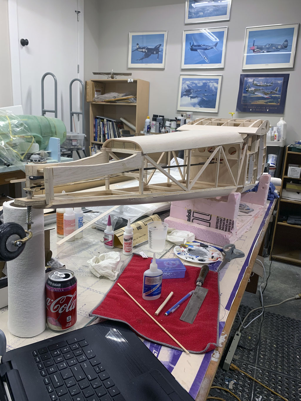
So if the linkages go to the elevator and the tail wheel, then where's the rudder servo? It's mounted within the vertical stab! And once again, an RDS linkage arrangement, this time for the rudder.
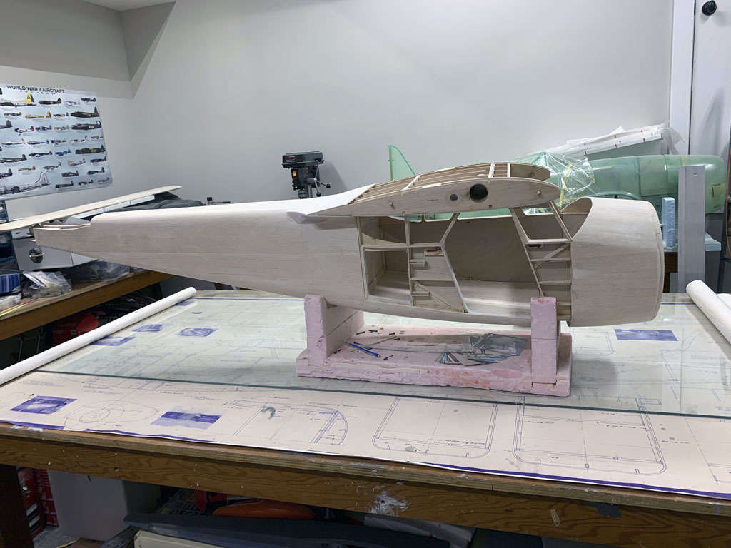
So next up in this build, the fuselage continues with more sheeting. Looks about finished but it's not. Now in this next photo we see the completed job from the left. It's fairly smooth and even has some filler.
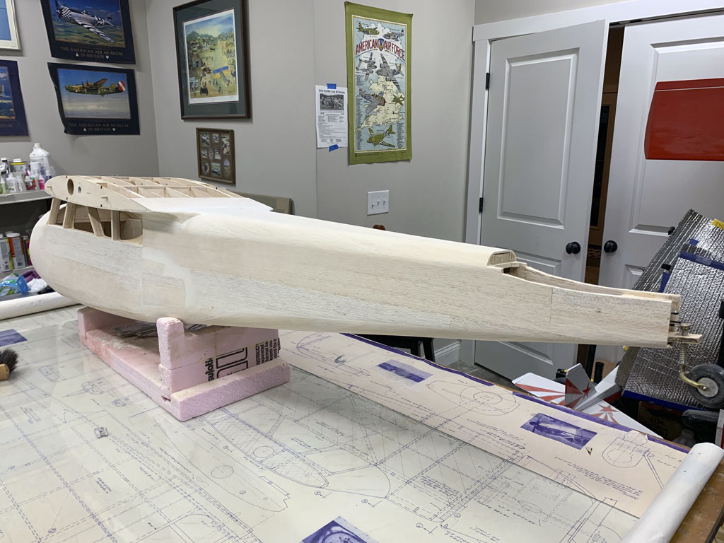
But when we look on the right side, here there's still sheeting to go. There are two sections of balsa sheeting remaining to be glued in place. These will cover the hinges so once it's done, there's no more access.
But before proceeding to button up the fuselage sheeting, the glazing remains. For this model it's relatively straightforward (unlike if you were to build a Fiesler Storch, for example).
This is also done with balsa and plywood for a lip against which to install the Plexiglass glazing.
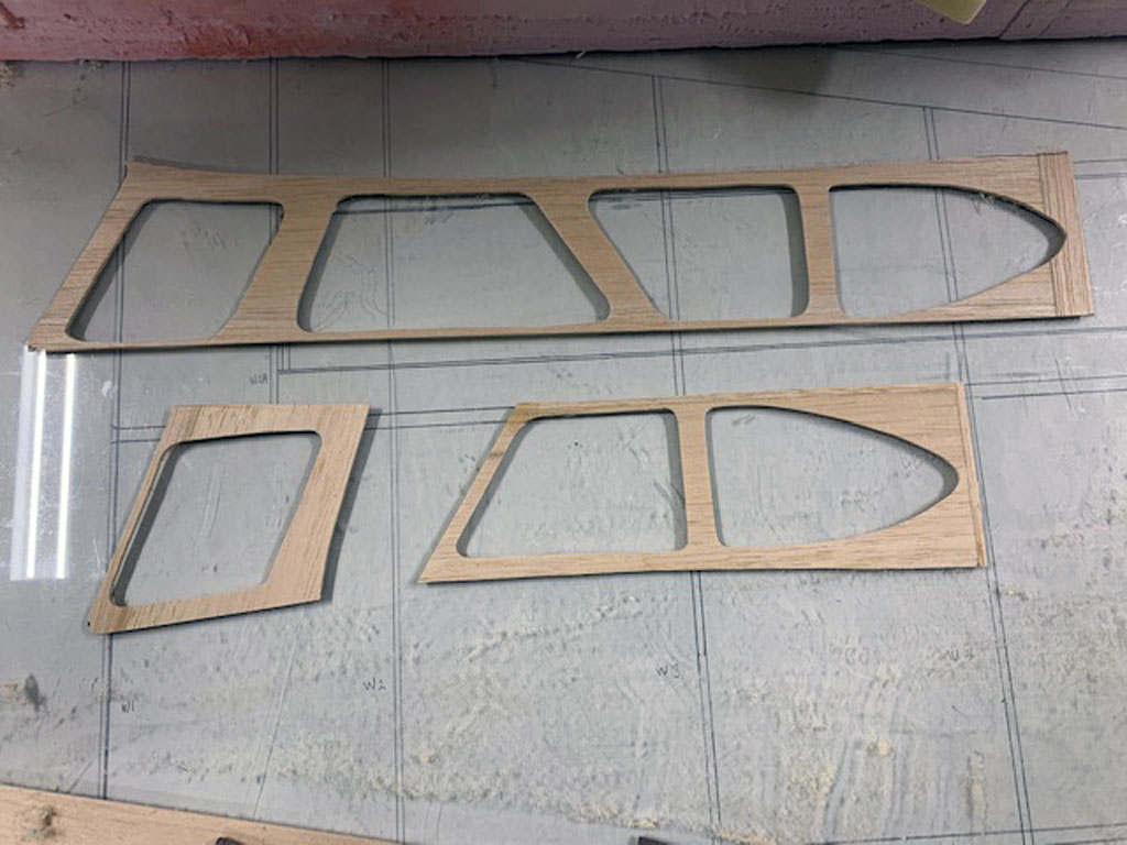
So in this next photo we see glazing installed. The balsa provides a lip for the glazing to sit on, while the plywood is the outer frame, itself.
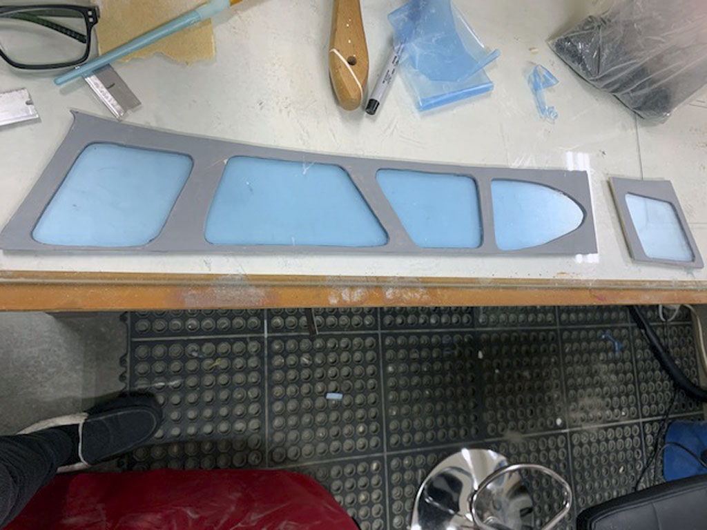
And now in this photo we see this frame installed into the fuselage.
Note; a small bit of filler is used to get everything ready for the glass-work - fiberglass.
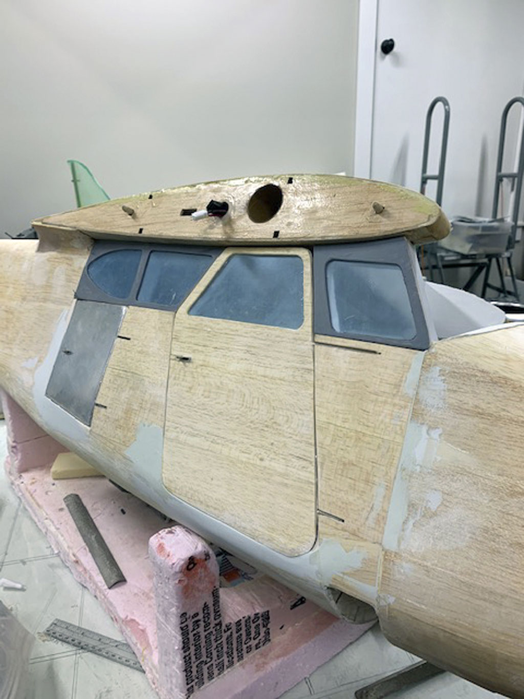
And this brings us to fiberglassing the fuselage just as the stabs and wing panels were. Once again 3/4 ounce glass cloth and resin. The benefit of laying in the green FrogTape is it give a clean cut line to which the cloth may be sanded where it overlaps that on the sides.
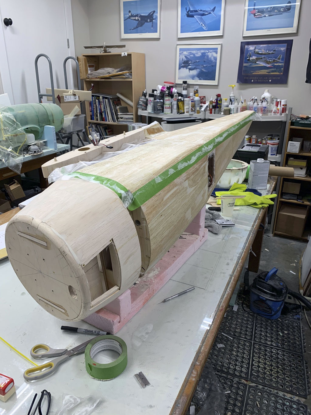
And in this photo, the fiberglass job is complete and now the model is ready for priming.
Note; as I keep saying look around within the photos and this time, eyeball some of the bit and bobs to finish the interior! Also notice the head of the bench top drill press just peeking up behind the fuselage along the wall. This becomes an important player in the story in a little bit. Oh, and the two red things? Those are the seat pedestals, or bases!
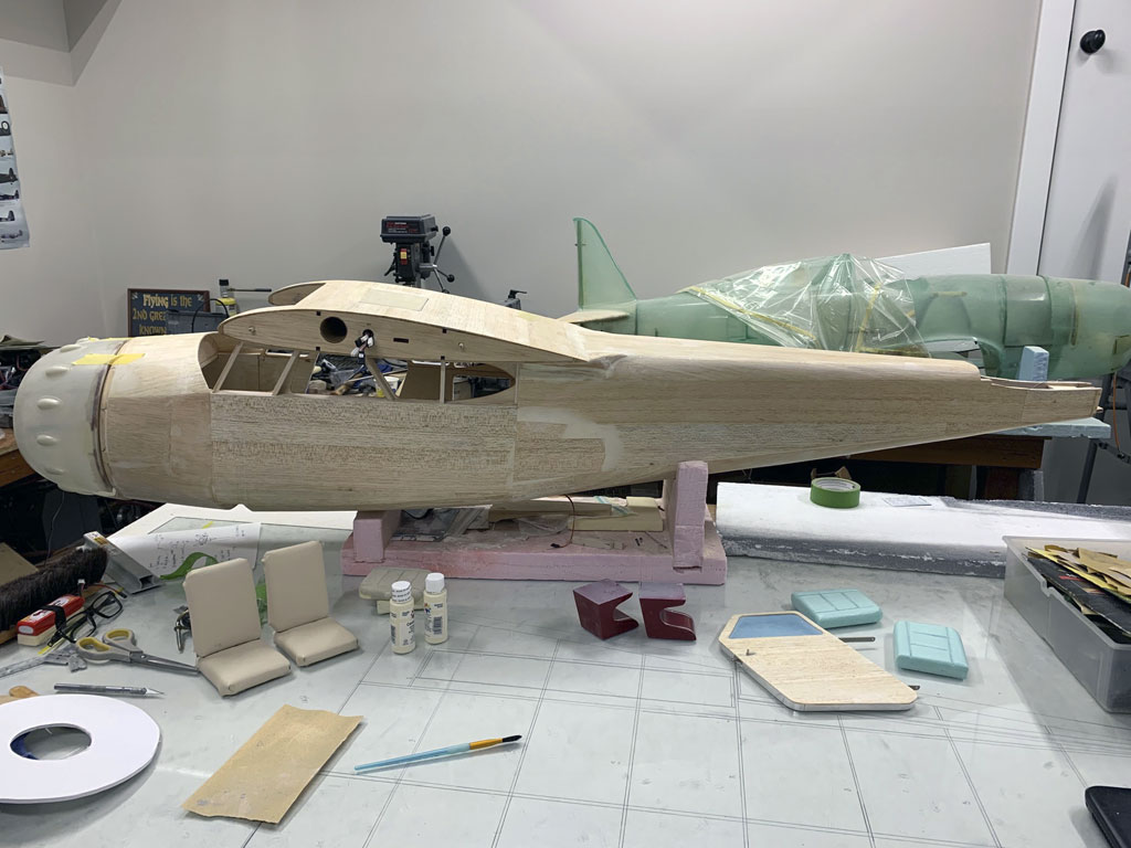
What else? Honestly? I've left out a ton of great photos - but - if I used them all nobody would read this article except me, and Matt!
As it is I feel I've been pushing the envelope of good taste. For example, back when the fuselage sides were finished, note how in this photo he clamped them together. What for? Simple, to work over the edges and ensure they were exactly the same!
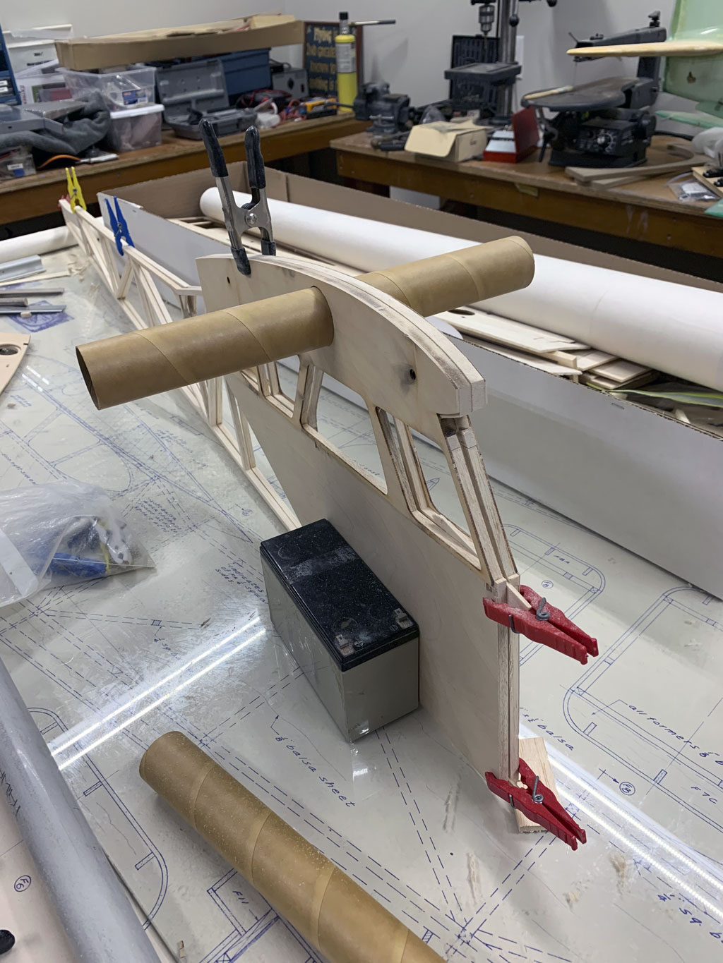
Like if you've ever built a model before, even a rubber power Guillow's kit, then you know to do this - but - if you're new to building, then this little step can save you a lot of grief, later. So I'm showing it because it's my opinion this particular model - maybe not finished to the level of this example - but the basic model itself, is not a terrible one which which to gain experience.
Saying as a first time scale build, there are worse. Anyway, since I've opened the door to the level of finish, let's walk through it and circle back to Matt's finishing the components. E.g. the stabs, wing panels, fuselage and cabin interior.
That will lead to paintwork plus nomenclature. Talking about the details!
Detailing - the finishing touches
So now we're going back through the model again because this is what brings the model to life!
The idea being to to show equipment installation, cladding the model in Flite-Metal, plus spraying the trim color, adding nomenclature, plus details like riveting the finish to simulate panels, as well as finishing off the cabin interior. Talking about the work he did with the seats, yoke, and instrument panel. That, plus little touches like the brake calipers that take this build over the top.
I'm not exactly sure of the order I'll show everything but since we've been eyeballing the fuselage construction, let's begin with it.
Fuselage
You've seen this photo, it's the first few pieces of Flite-Metal Matt attached. As for the low tack green FrogTape, Matt's using it to establish panel line position because it doesn't leave residue after removal. So in this photo, as he works along the bottom from the tail post forward, the second piece is attached and burnished into place.
Also, if this is metail is floating your boat and you want to know more about the techique, Ed's shared this a YouTube playlist titled:
Note; the model has been primed and sanded as if for paint. As with every paint job, the goal is to make the surface as perfect as possible because paint doesn't hide anything. It's the same in spades for Flite-Metal because EVERY imperfection will be magnified!
So in this photo, as Matt's working his way forward along the bottom aft part of the fuselage, the seams overlap smoothly 'with' the slipstream. It's why you work your way forward. And because it's shiny reflective stuff you're even going to see dust that lands on the surface. Don't worry about it, the overall job will turn out fine. Saying don't get wrapped around the axle regarding imperfections.
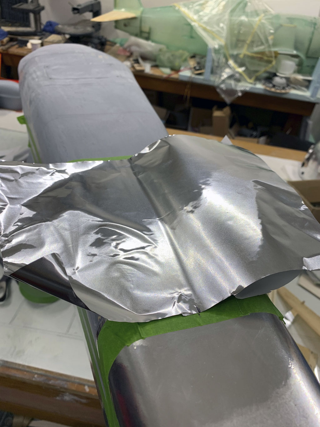
Now in this photo you get a better idea of the character of the sticky back material. And here's a tip, just as when working with MonoKote, extra material to grab hold of to pull is a good thing. If you're only going to be seeing dollar signs and thinking of this excess as waste, then stop, grab an adult beverage, sit and ponder what I'm saying and adjust you attitude.
You 'need' to be able to pull and work it into place and as you burnish it down. Trust the process. And remember, there's basically no stretch, this is a lot like aluminum foil.
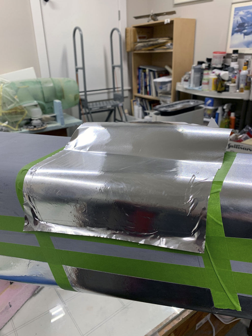
Now in this photo, the piece above has been trimmed and is being burnished. You must be patient and have reasonable expectations.
Note; do see the edge impression of the FrogTape? This is where you make your cut, so it's serving as a witness mark!
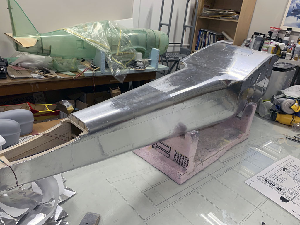
So piece by piece, you plan the work and then work the plan. Have faith your patience will be rewarded with something that looks like this when the basic Flite-Metal is applied. But there's more to it, so hang loose as we proceed.
Empennage
So the stabs are next (the fixed horizontal stab and vertical stabilizer combined with movable elevators and rudder are termed empennage). We'll begin with photos of them primed and sanded to shape and now having been cut for the elevator trim tab.
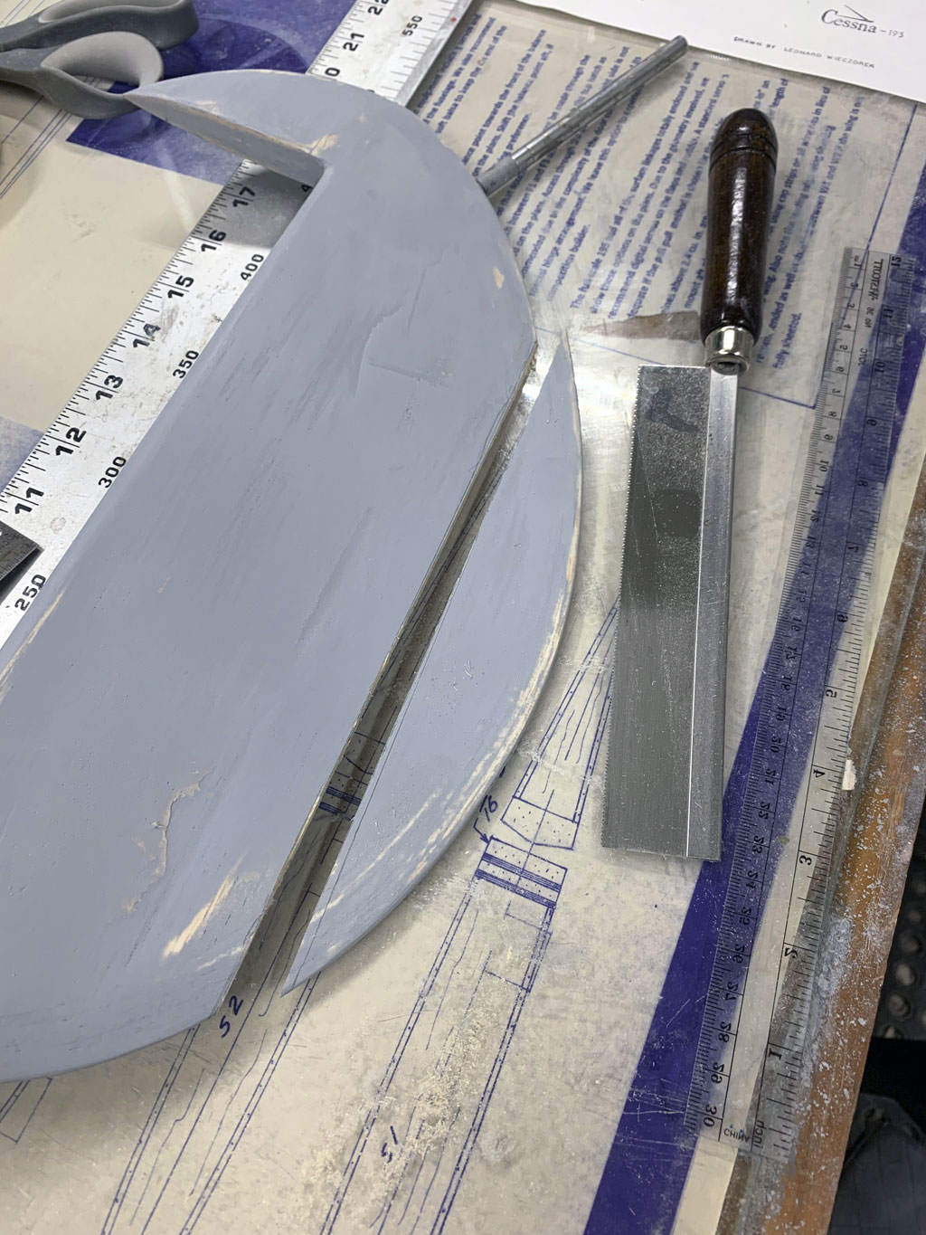
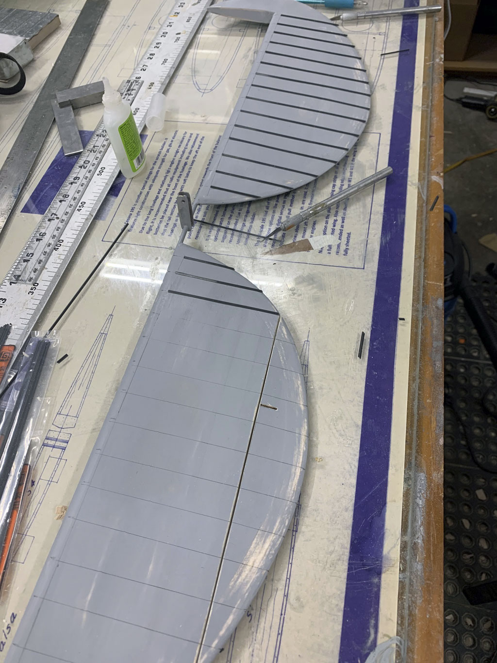
In this next photo, Matt's drawn pencil lines for where he is gluing the strips to represent the corrugations. Cessna is famous for corrugated metal on both their rudder and elevator surfaces, and they continue using it to this day! Point being, replicating the corrugation is required in order to pull this model off with style.
What he uses is Plastruct triangular polystyrene extrusion. They offer it in more sizes than Carter has liver pills (slight exaggeration) so it's just a matter of finding what works for your chosen scale.
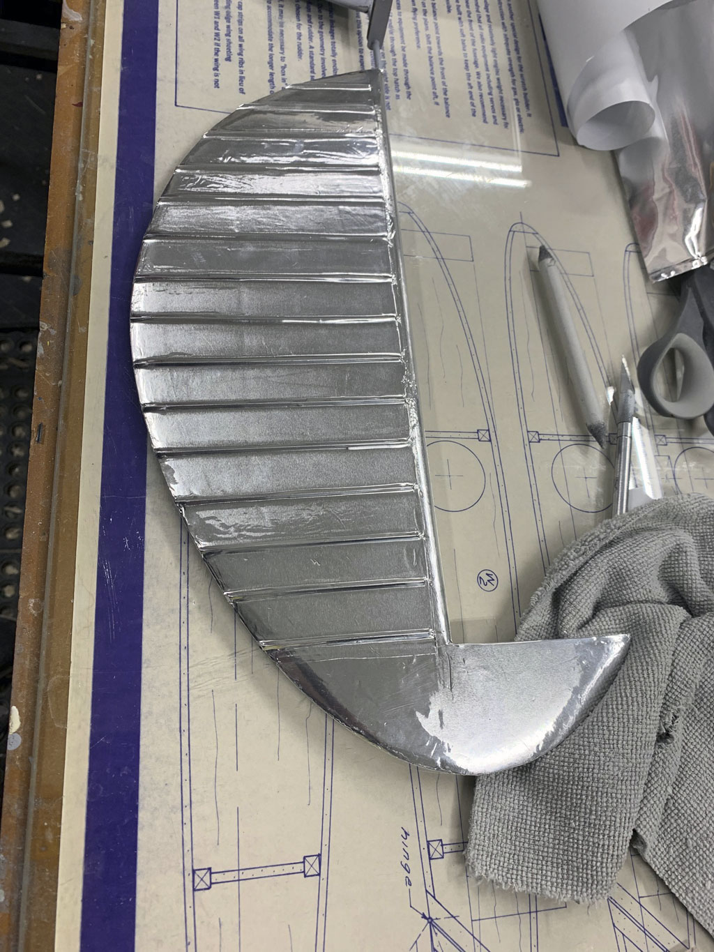
Anyway, once you patiently apply Flite-Metal to the surfaces, the corrugations look utterly convincing. And now the model begins to come to life.
But wait, it gets better.
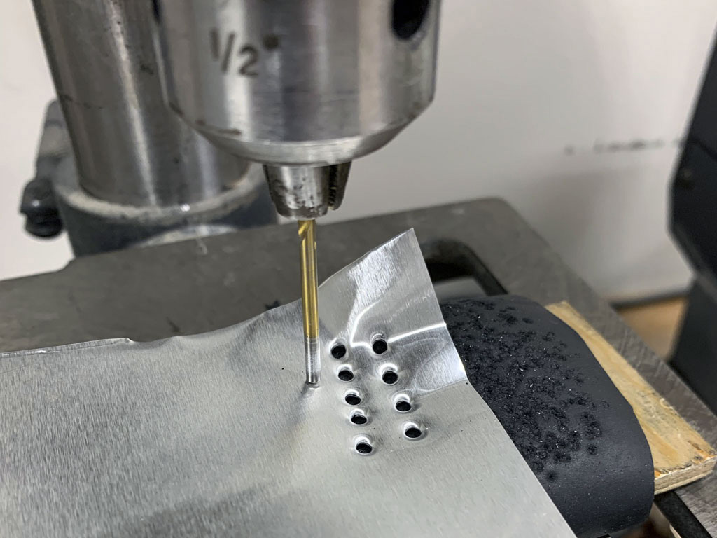
Remember I mentioned the bench top drill press? Matt makes use of it to make rivets using hardware store aluminum flashing. How? Simple, he reverses a drill bit within the chuck, and drills holes using the wrong end of the drill bit by melting through the flashing. The flashing is backed by hard rubber which lets the alloy stretch and form the dome shape.
What this does is press out rivet heads, which are very realistic. And he patiently makes them by the hundreds.
Then once he has enough, he gets started. What's enough? Dunno, but I'd estimate hundreds if not thousands! Just look in the lid of that servo case he's using as a storage bin.
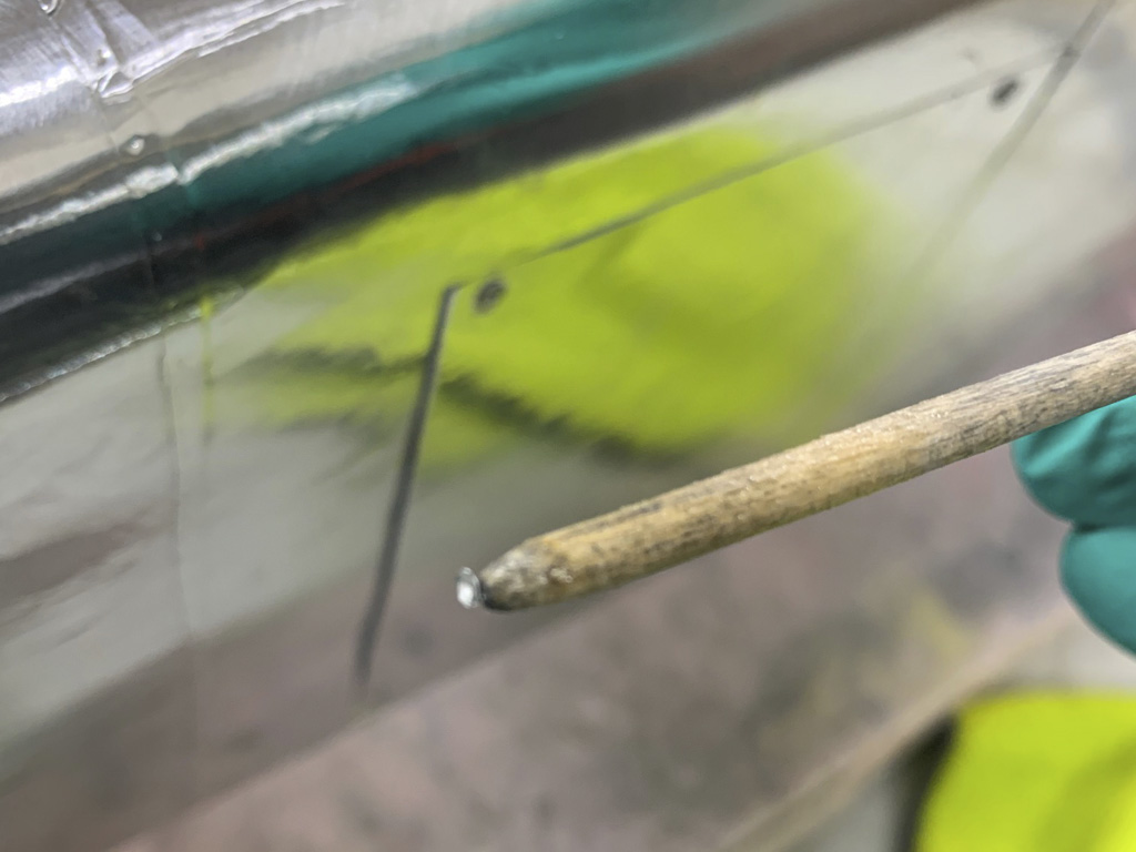
So to the question of how he applies them and get them to stick, look at the rest of this photo. The thin dowel on the container with water is the key. The other piece of the puzzle is the container with epoxy, except it's not epoxy, it's clear Klass Koat paint.
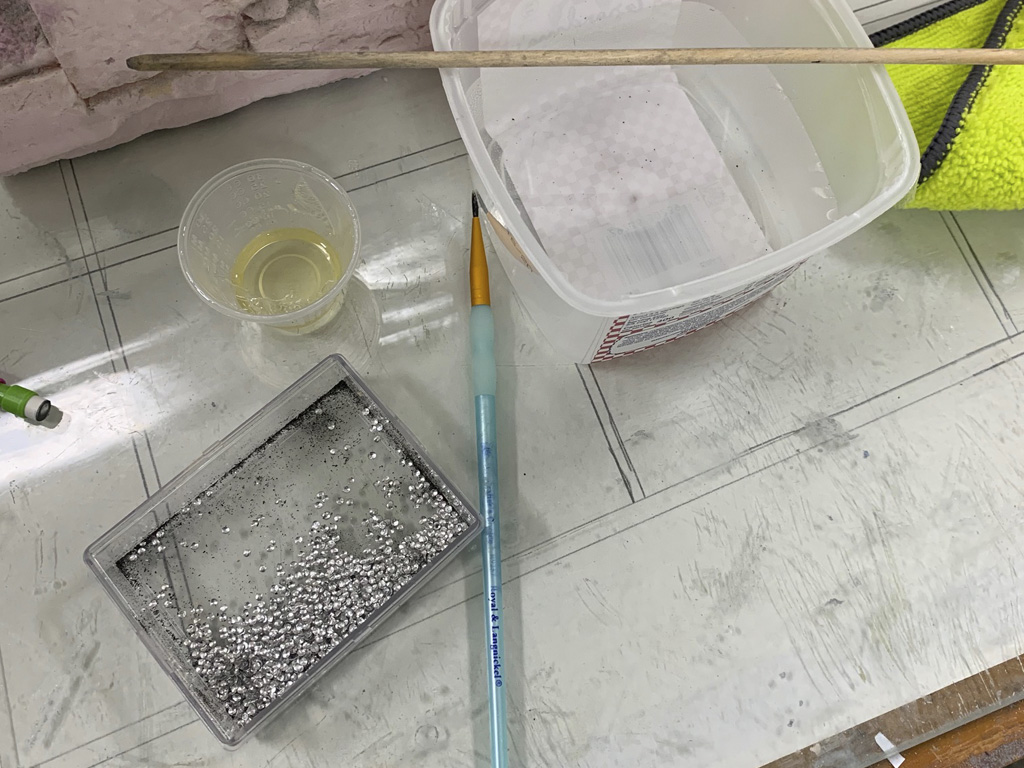
So what he does is pick up a simulated rivet head and glue it in place with the tip of the dowel.
And what results is simply magnificent!
Remember, this is extreme close up photography, so you're going to see flaws and imperfections you won't notice in real life.
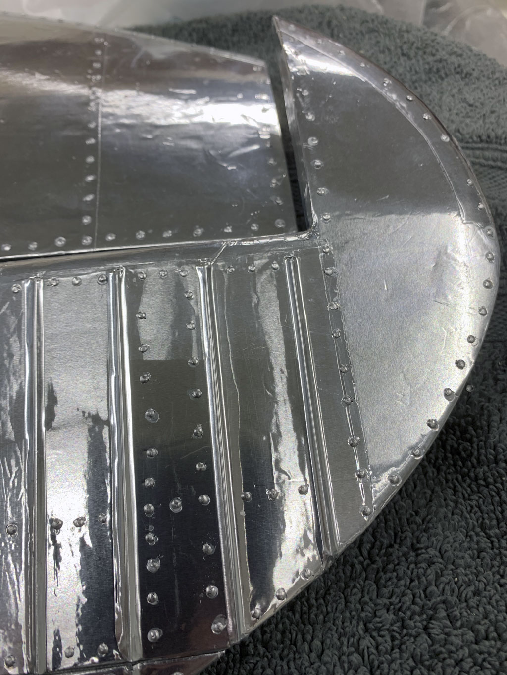
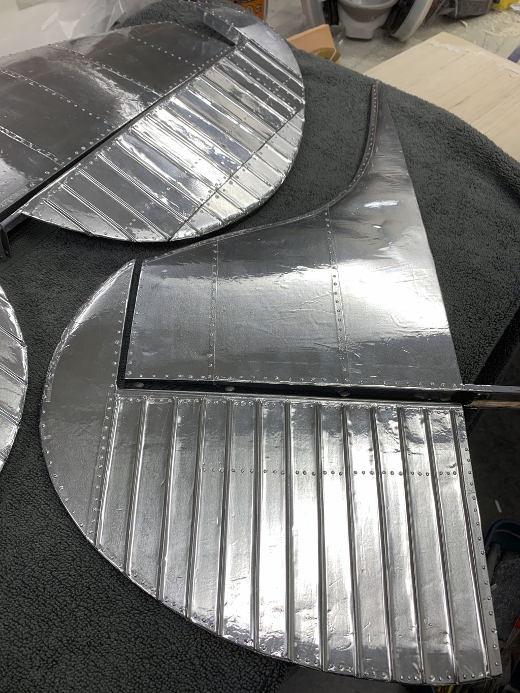
Now let's pull back a little bit, do you see how the combination of the aluminum surface, the corrugations, plus the rivets look simply outstanding?
Wings
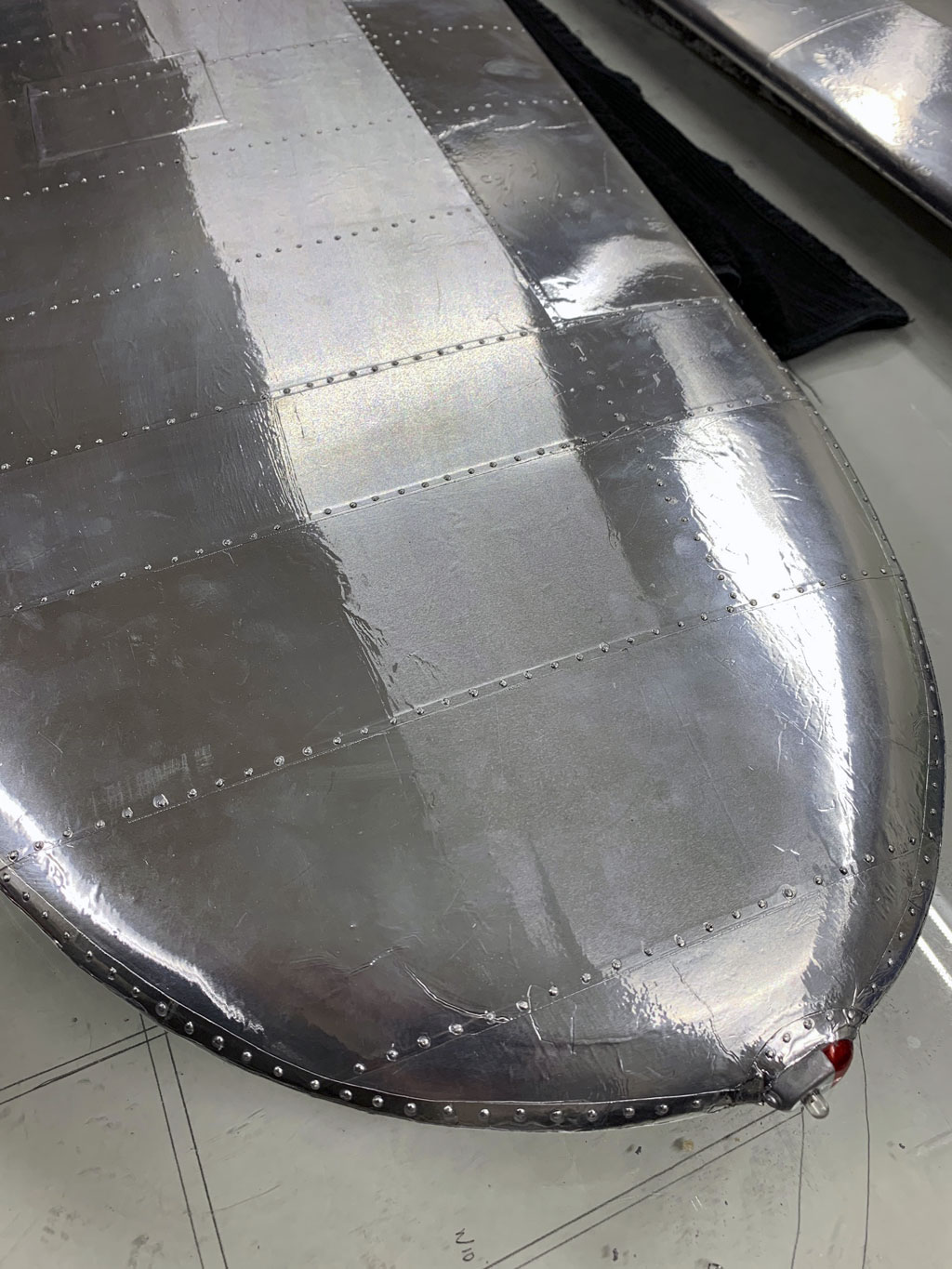
So now let's go to the wings. Again, the attention to detail is simply magnificent. We'll begin with a close up of the wing tip.
Every single alloy panel on the full scale aircraft is replicated in miniature. Rivets bring the whole thing to life. Yes, I've said this before but my goodness, just look at this!
And remember, you want to look closely at the details. Remember the cardboard tube leading to the wing tip? Eyeball the navigation lamp on the very tip. Fantastic, yes?
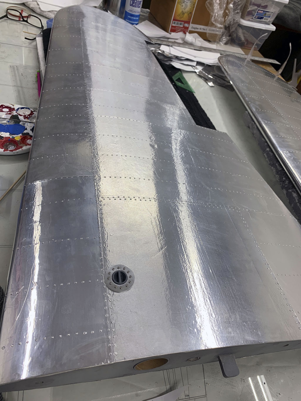
So in this photo we see the entire upper wing surface. The sheer tenacity Matt has, the dogged determination to see a project through is also on display. But eyeball the fuel cap, is that sweet, or what?
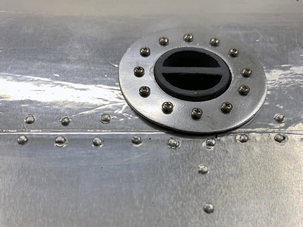
So here's the gas cap and the flange surrounding it in an extreme close up photo. This allows us to better appreciate the work involved.
cowl
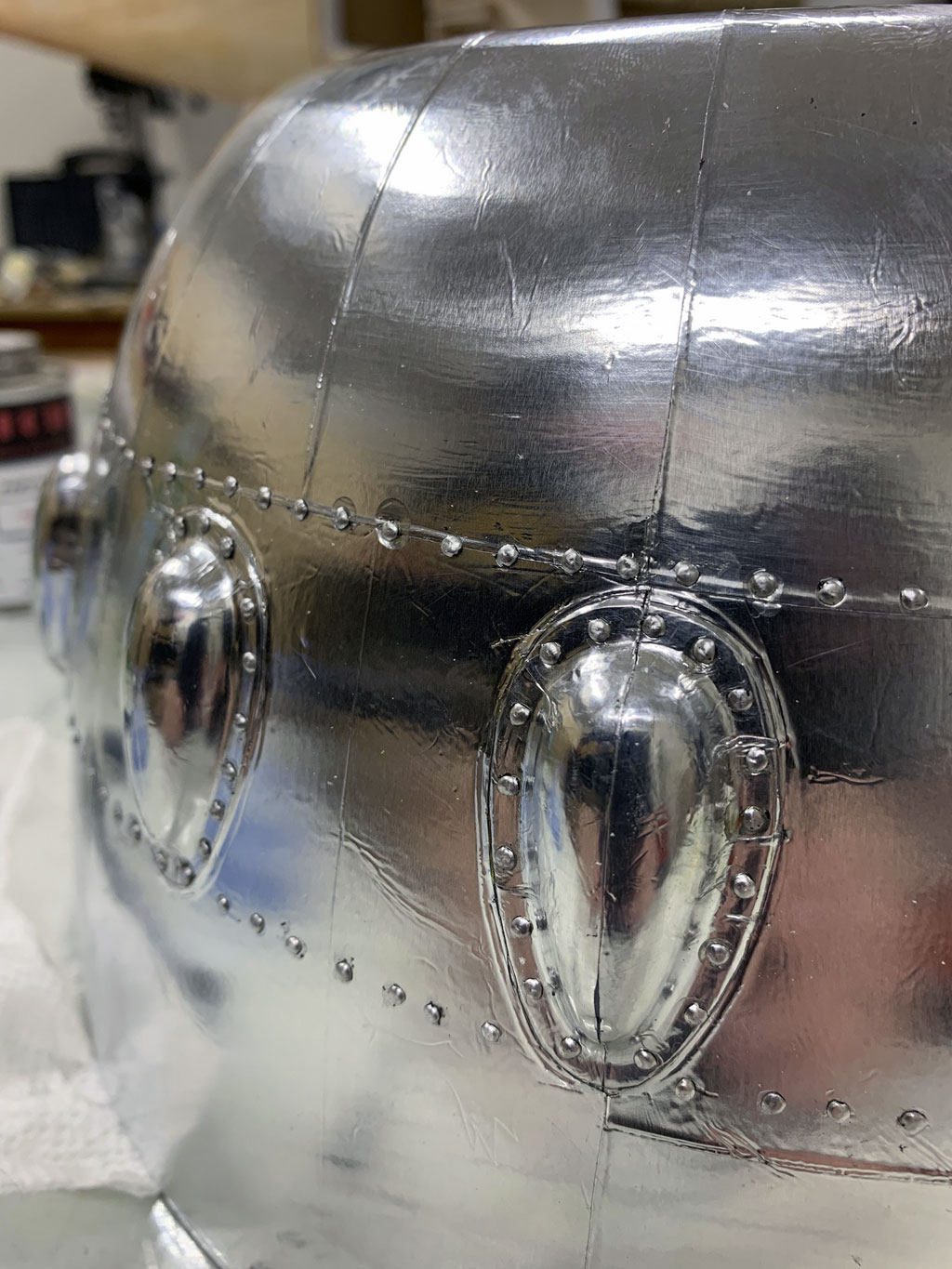
Next up is a nice detail, the cowl. it begins life at the hands of Fiberglass Specialties as their part number WH-35.
So first up, Matt began by doing the individual bumps for the valve train. Since this represents a model with a 7-cylinder engine, then two valves per cylinder means 14 individual projections to be covered.
Total pain in the ass job because of the tiny compound curves! But there's more.

Next comes the cowl surface itself. This is covered in sections and are really tough because of the compound curves. Remember, the Flite-Metal is real aluminum, so stretching it around curves and burnishing it place isn't easy and takes determination.

But the final result is so worthwhile!
Interior
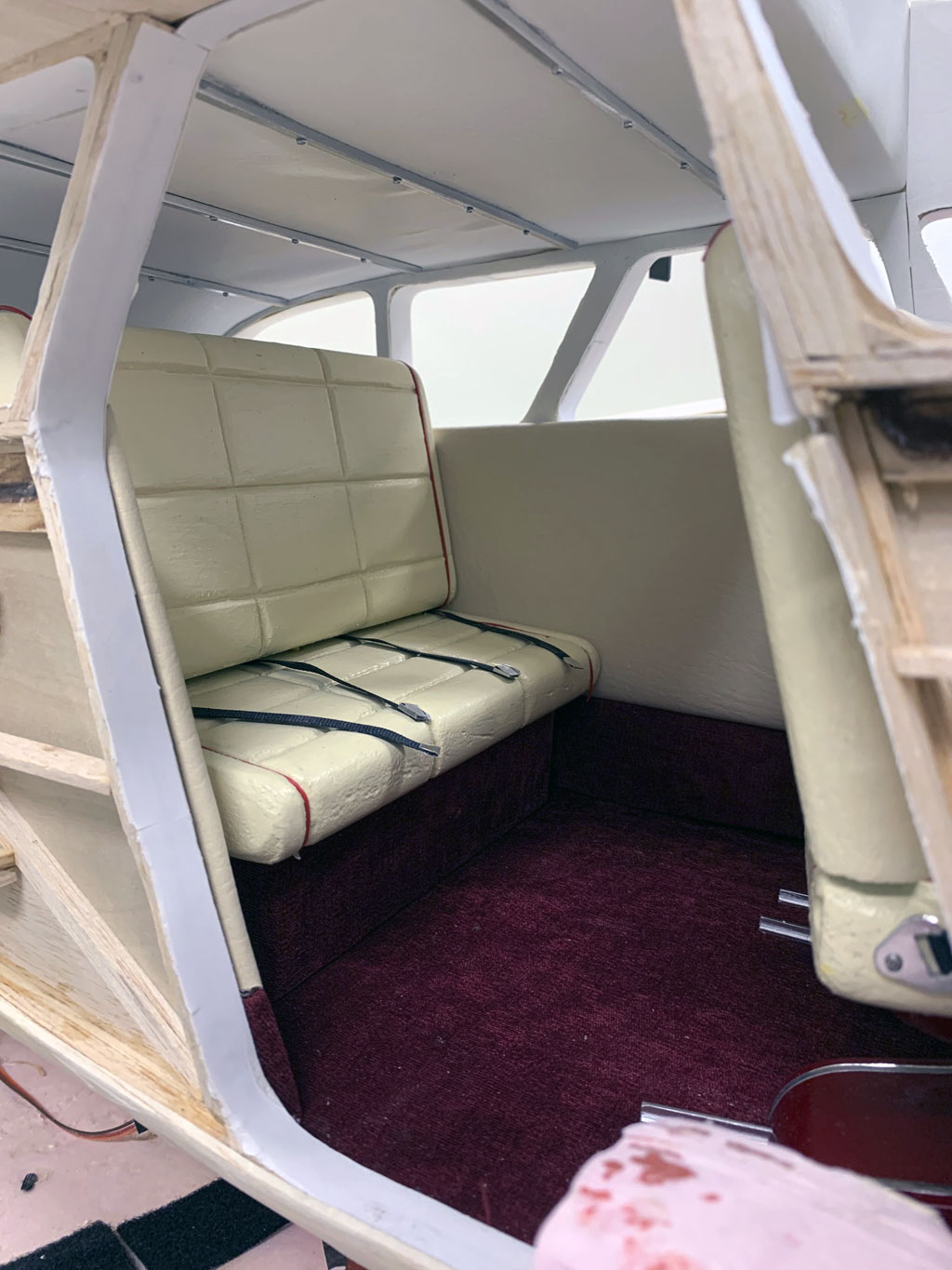
Next let's show a few photos of the interior as we move to wrap this up. We begin with a shot looking aft through the main cabin door. This is what you see as a passenger before embarking.
Note; the side panels, carpet, the rails in the floor for the seat tracks, even the headliner rails are faithfully reproduced. Ditto the piping trim on the seats and the seat belts.
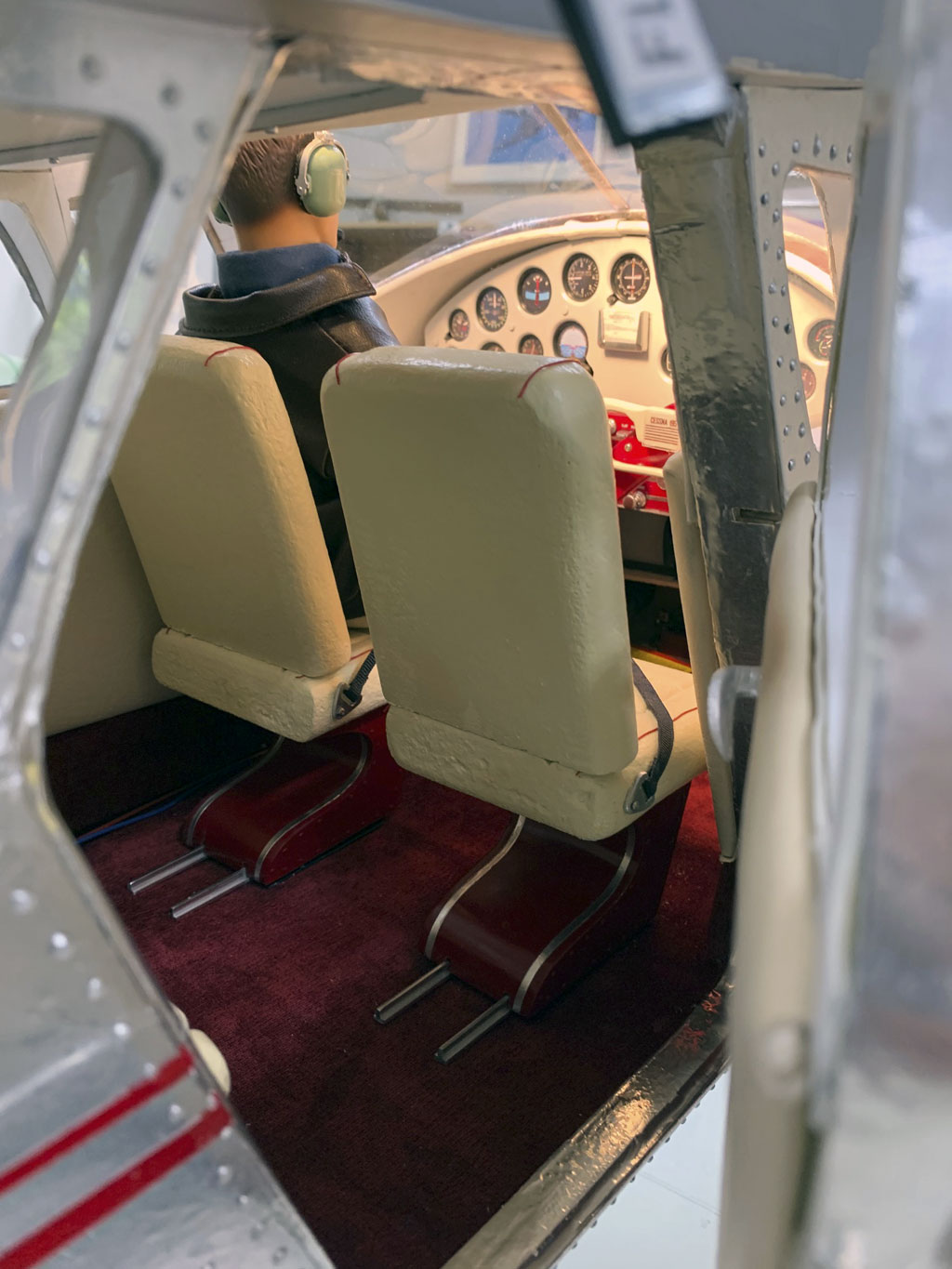
Now looking forward, the the pilot with green David Clark headsets, the seat pedestals, everything is perfect!
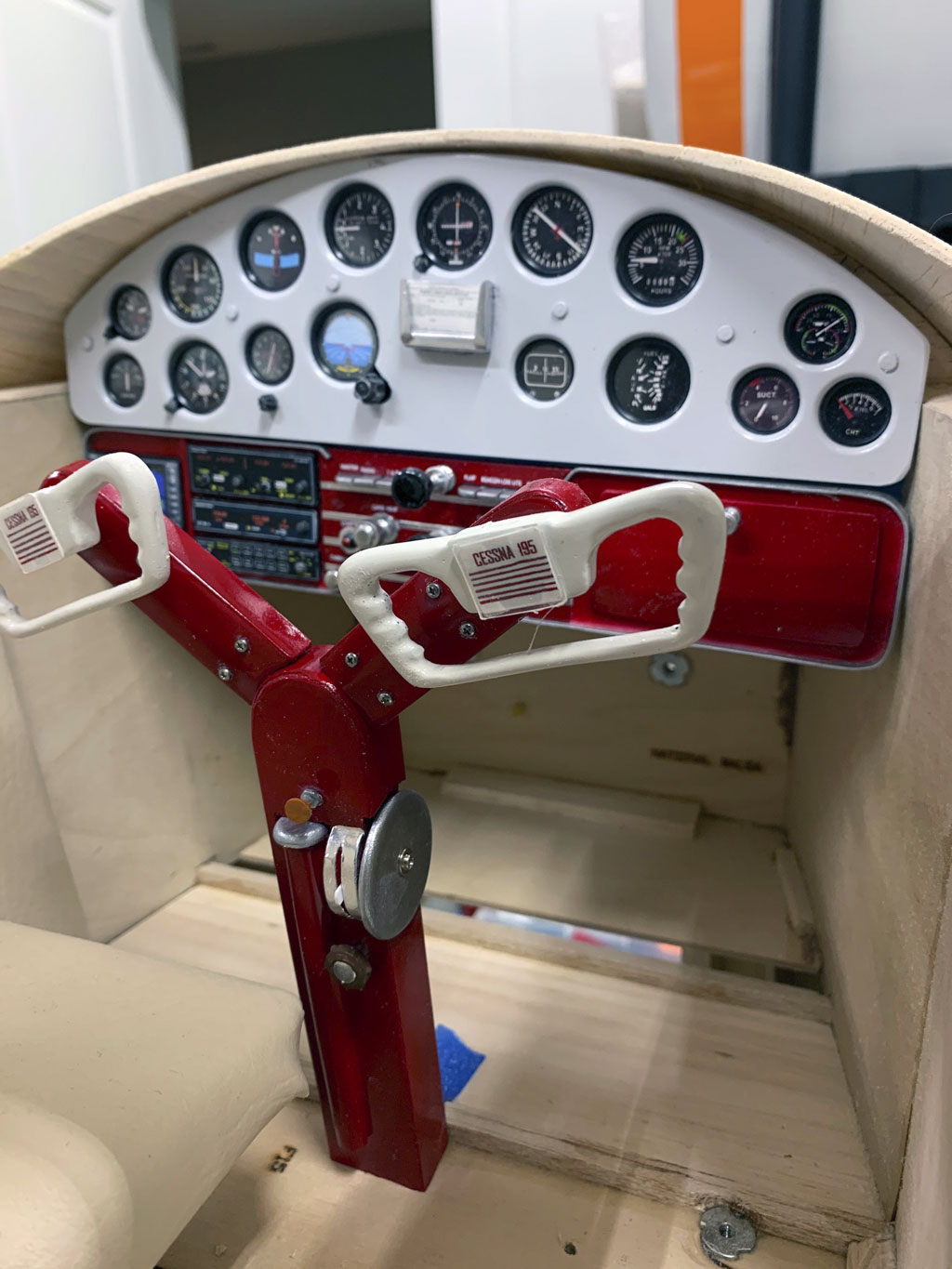
Now take a gander at the instrument panel. Speechlessness is appropriate.
There's so much to see. Most focus on the instruments, and that's fair but as a pilot, I notice the throttle and mixture controls, the radios, the yoke details. Even the button on the glove box door!
Note; he's even replicated the trim wheel on the control column!
Paint and nomenclature
So bringing this to a close, let's look at painting and nomenclature. Yes, the model is replicated in alloy but there's still paint and lettering to do.
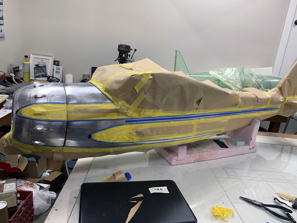
In this photo we see the model masked off for paint. While it almost seems a shame to cover any of this thing, Matt is on track to replicate a specific aircraft, so he's got the color nailed and is ready to shoot paint.
This is the aftermath of spraying. Questions abound. For example, will the masking release cleanly or will it leave an ugly edge? Honestly, it's a time of reflection and not a little trepidation.
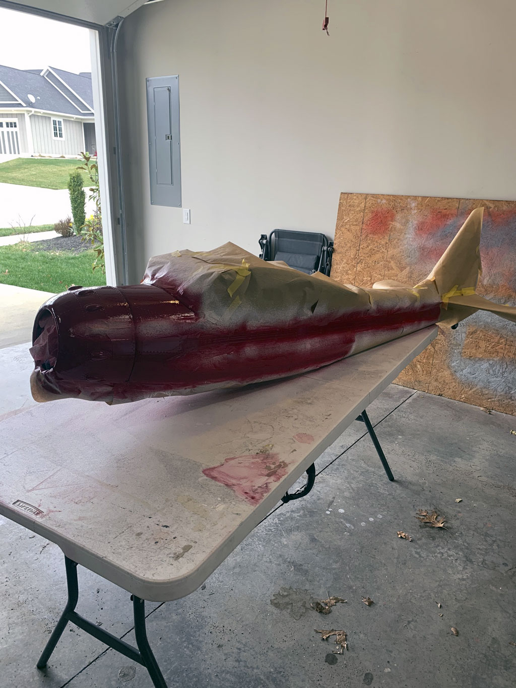
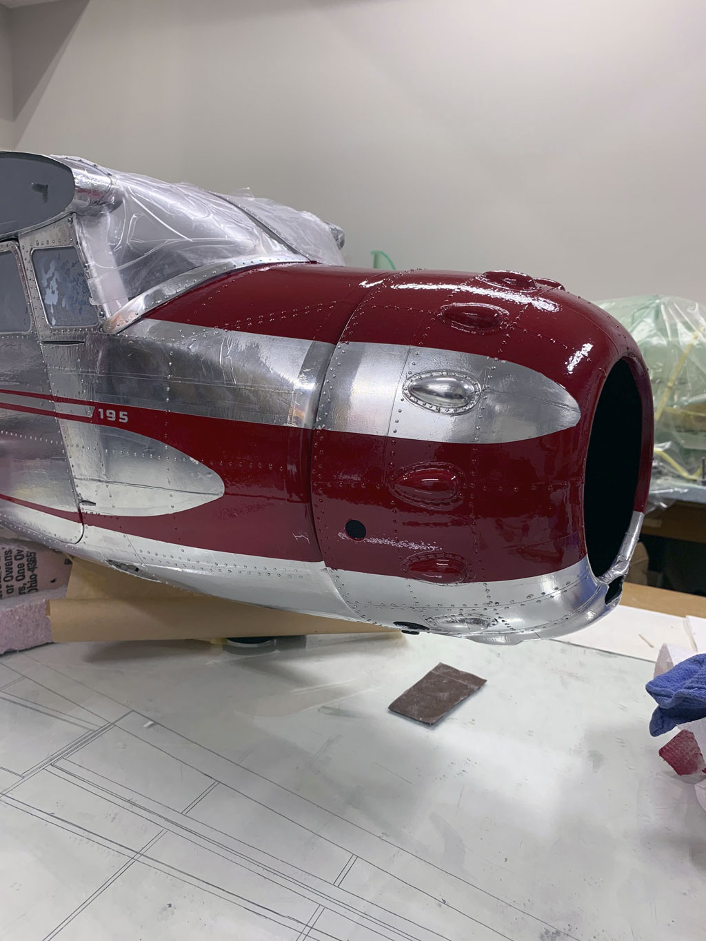
Afterwards, it's a yeehaw moment! The forward fuselage came out really, really nice. And eyeball how cleanly the 195 separated on the stripe. Sweet!
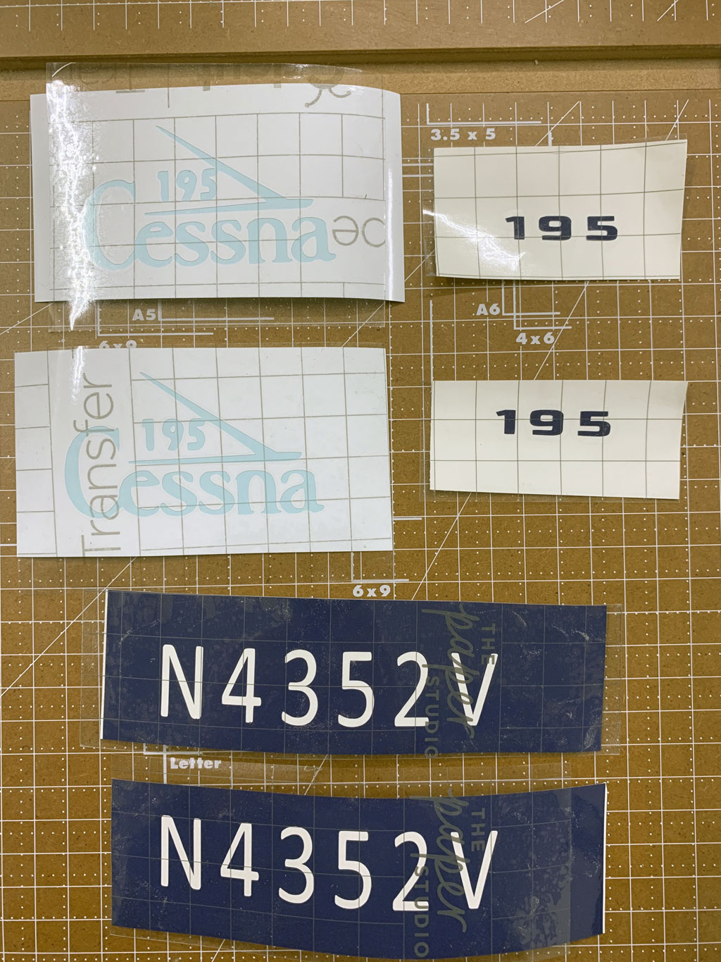
For that numbering to separate so cleanly required paint masks.
The nomenclature consists of N-numbers, model numbers, and of course, logos.
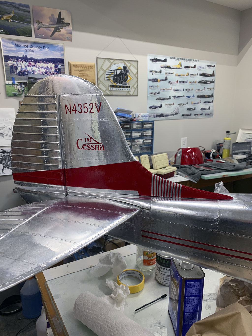
And it's the same story on the aft part of the fuselage because the paint laid in nicely, the masks separated cleanly. It's simply gorgeous!
Brake calipers
A detail I promised to share and left to the very end are the brake calipers. Earlier I shared a photo of a full scale 195 and mentioned how visible they are. So that Matt replicated them on his build is totally in character.
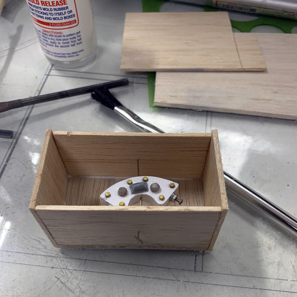
Now in this close up photo, you see the prototype brake caliper within a balsa box in preparation for molding. The mold release is the bottle beside it. Look closely and you'll see a large T-pin penetrating the box and suspending the caliper off the bottom so it is fully encompassed when he pours the silicone for the mold.
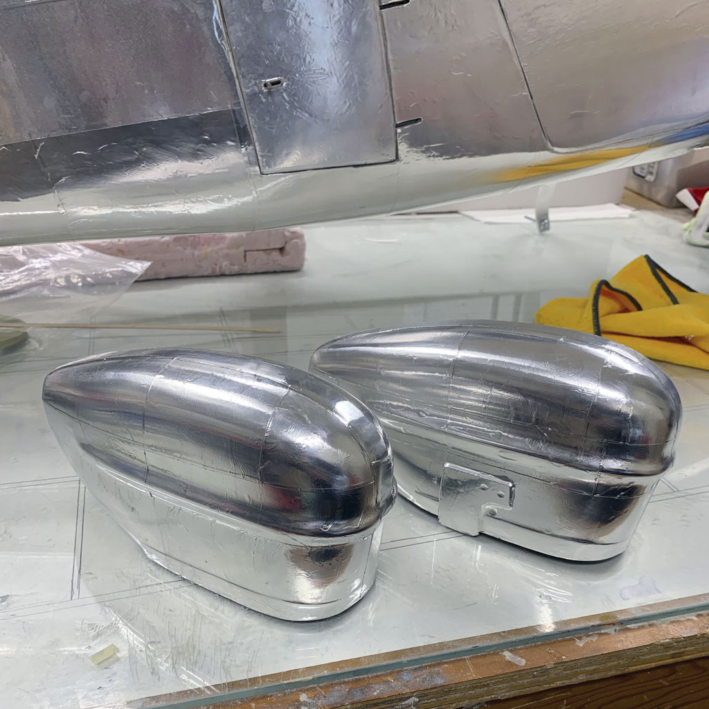
In this close up photo we see the wheel pants after the application of Flite-Metal and what you should take a special interest in is the bracket for the brake calipers.
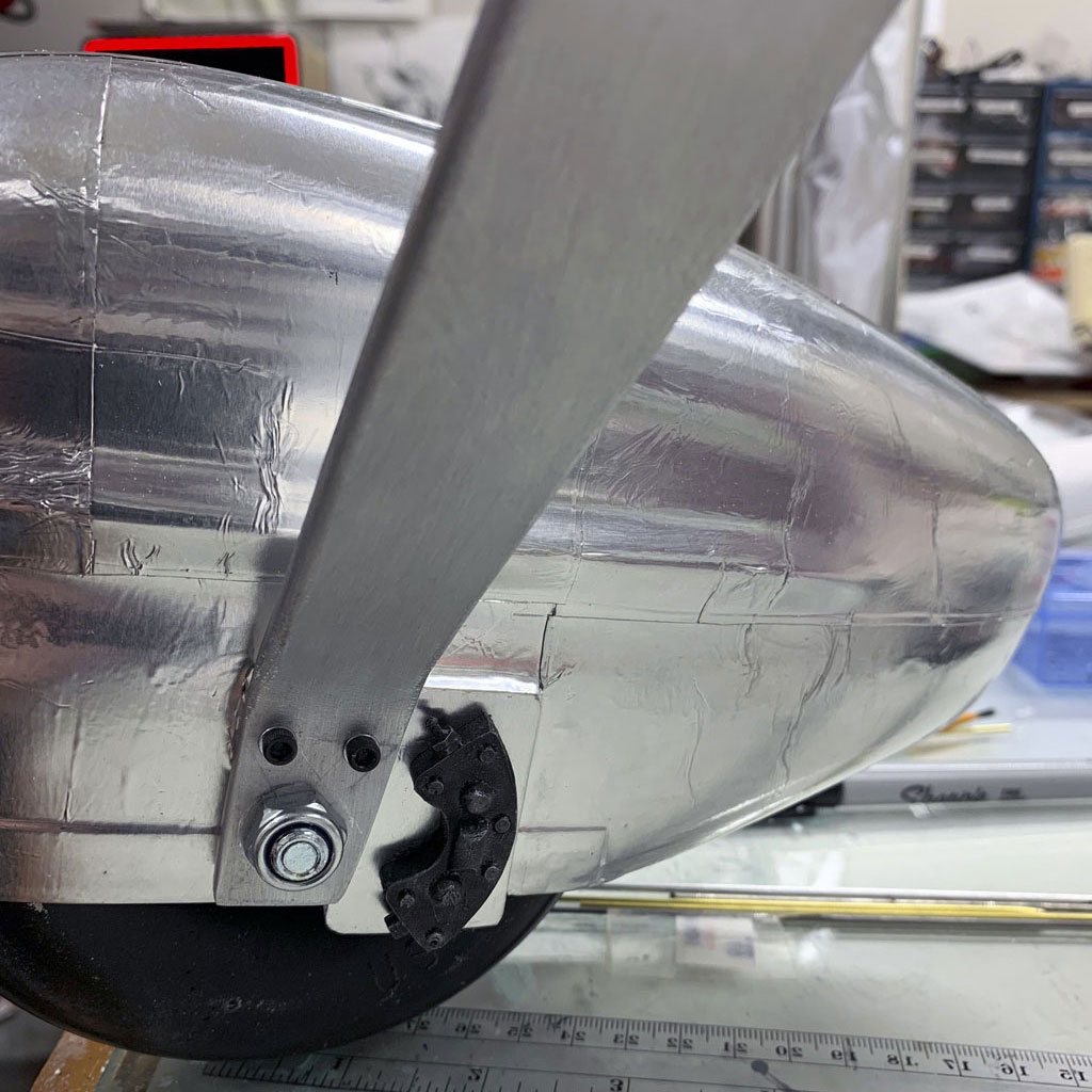
And here we have the final assembly replicating the real thing. This close up photo shows the brake caliper affixed to the wheel pants of the Hostetler Cessna 195. Yes, it's a small touch, one that's easily dismissed as not worth the effort except in this case, this guy finds 'everything' worth the effort!
Avionics
So I promised to stop yacking about servos, and I've largely kept to what I said (besides showing them during RDS installation, but that was ancillary to the purpose). Anyway, now, as we're nearing the end of this article, we come to the final photos. These include the avionics installation. Inevitably this involves showing the servos, too. Plus receiver, batteries, switches, gyro, etc.
It's a nice and neat installation, agreed?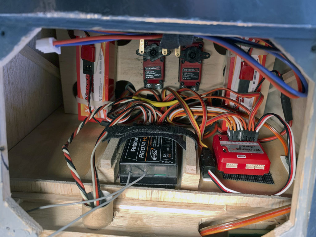
Conclusion
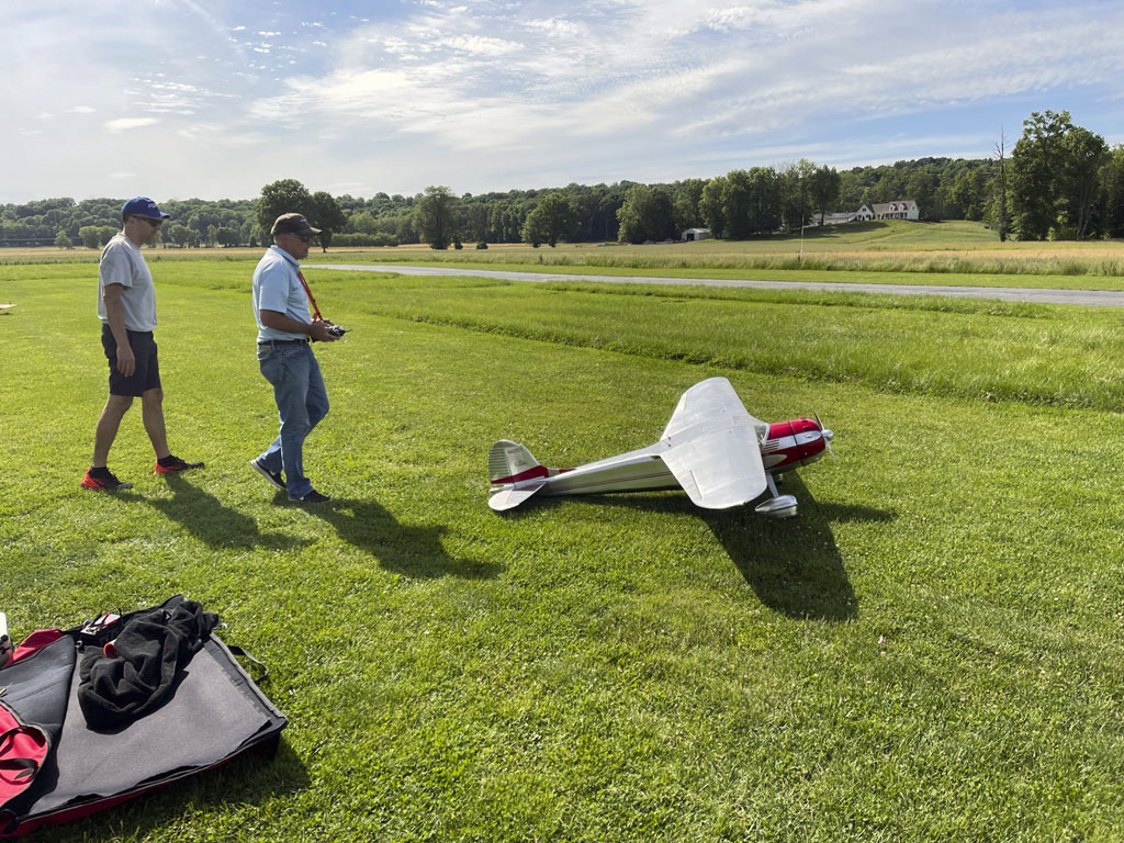
So let's wrap this up. We started out to tell a story of a labor of love. And we'll close it simply with this photo of 'da man and his model. This is Matt Fornefeld and his Hostetler's Plans Cessna 195 as they taxi out on the grass to take the active runway on a lovely hard surface runway.
Final note, I've related this story to the best of my ability, any errors or omissions are mine, and mine only.


