
So the other day I got an email from Andy Johnson of Albuquerque, NM. He's a long time customer and wrote . . .
I have acquired a TopRC Zero, with a 93" wingspan. I'll be using a Saito FG-90R3 radial so it's not going to be a speed demon. What servos would you recommend for typical warbird flying - no crazy stuff?
. . . and because I wasn't familiar with the model, first thing I did was visit the website of TopRC Model in Guangdong Province, China to download the manual. While there I poked around and learned they've been doing this since 2014 and in the process have become the largest manufacturer of composite airframes in all of China. No small feat. More later.
Anyway, I know Andy more as a builder instead of an ARF-guy. Like this fellow is seriously passionate about his warbirds! For example, the model before this one was a fantastic labor of love. Talking about a multi-year scratch built Ziroli F6-F Hellcat powered by a DLE 222 (four-cylinder) driving a Falcon 28.5 x 12 three-blade prop (and yes, equipped with ProModeler servos). And believe me when I say it's a hoss!

- A small touch, but eyeball the wheel chocks

Point being, I knew if I could persuade Andy to share a few photos we might see an interesting take on what is usually just another weekend project. Anyway, once I familiarized myself with a few details of the servo installation, I was ready to help guide him. And this turns out to be easy because facts are, pretty much all 5th scale models are going to use almost the exact same-same avionics.
Yes, there will be differences in the length of the extensions; for example, this model uses a pair of extra long ones because the elevator servos are parked within the horizontal stabs. Ditto, some differences in the servos arms because these are largely dictated by how the servos are mounted within the structure.
Locking extensions
Oh, and heads up, if you order extensions from us, we offer locking ones, too (a drop down menu selection when ordering). Point being, these are the ones you want wherever you cannot inspect the connection.
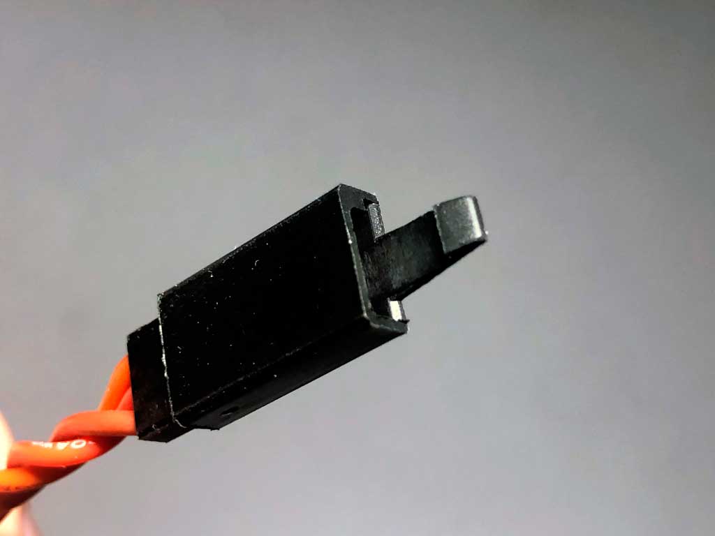
- Locking extensions are quick and easy to use
But as regards the basics, the servos themselves? Servos for a 25-30 pound warbird are pretty much going to be the same between like size models. Point being, over the years, we have developed three avionics recommendations for this class of model. And for our part, we refer to them as good, better, and best. And before you ask, the answer to which is best for you is, as always . . . it depends!
Anyway, here goes, the 5th scale warbird avionics list.
Avionics
Good - Servos and arms
- 2) DS180DLHV - ailerons
- 2) DS360DLHV - flaps
- 2) DS360DLHV - elevators
- 1) DS270DLHV - rudder
- 1) DS90DLHV - throttle (plus another for choke)
- 2) DS90DLHV - inner gear doors
- 1) DS90DLHV - retract shuttle valve (delete for electric)
- 6) PDRS25L-25T - flight controls (less rudder)
- 2) PDRS101 - Heavy Duty Polymer servo horns (gears doors)
- 1) PDRS105 - Anti-vibration throttle arm
- 1) PDRS50PP-25T - Pull-Pull (rudder/tail wheel)
These DL-series servos we're guiding you to are offered in a range rated between 90-360oz-in of torque. If there's one thing folks especially appreciate it's the finned aluminum center case because they run cooler on hot summer days than all-plastic.
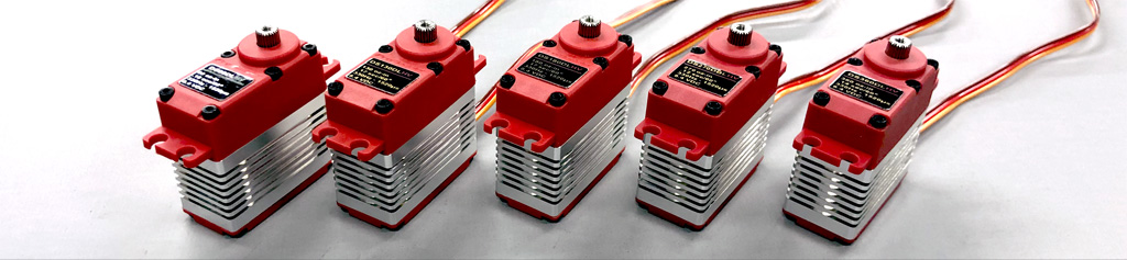
Better - servos and arm
- 2) DS360DLHV - ailerons
- 2) DS360DLHV - flaps
- 2) DS505BLHV - elevators
- 1) DS360DLHV - rudder
- 1) DS90DLHV - throttle (plus another for choke)
- 2) DS90DLHV - inner gear doors
- 1) DS90DLHV - retract shuttle valve (delete for electric)
- 2) PDRS101 - Heavy Duty Polymer servo horns (gear doors)
- 6) PDRS25L-25T - flight controls (less rudder)
- 1) PDRS105 - Anti-vibration throttle arm
- 1) PDRS50PP-25T - Pull-pull (rudder/tail wheel)
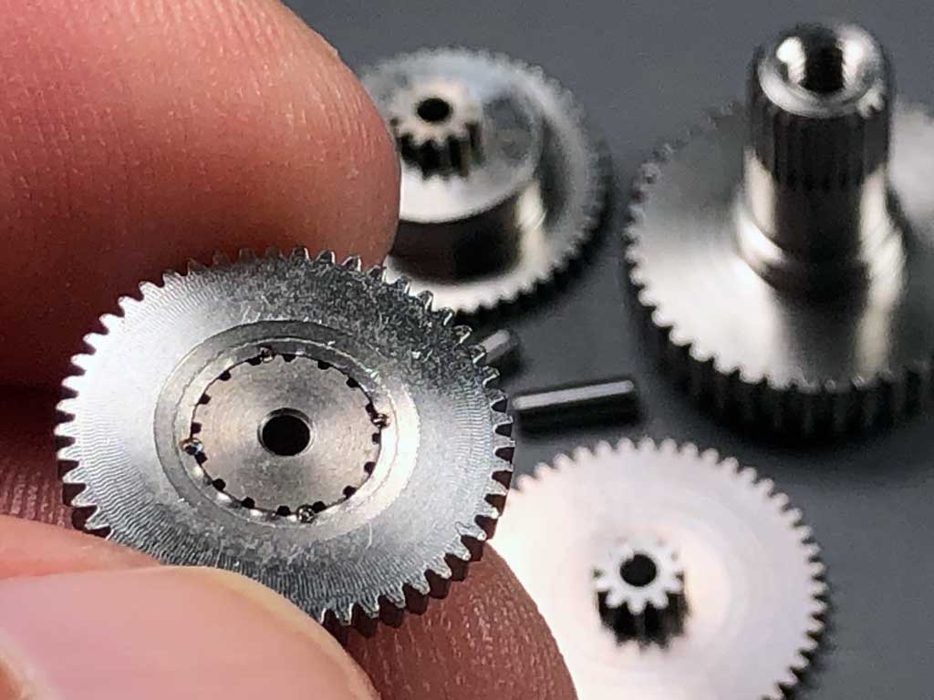
Here's another detail folks appreciate about the DL-series servos. To get a great price, we agreed with our gear hobber to use the same-same durable stainless steel gear train across the lineup (because this increased their sale volume).
What this means for you is you get the same four spot-welds for added durability between pinion and bull gears as in our top-of-the-range all-alloy servos.
Best Servos and arms
- 2) DS505BLHV - ailerons
- 2) DS630BLHV - flaps
- 2) DS630BLHV - elevators
- 1) DS505BLHV - rudder
- 1) DS90DLHV - throttle (plus another for choke)
- 2) DS90DLHV - inner gear doors
- 1) DS90DLHV - retract shuttle valve (delete for electric)
- 2) PDRS101 - Heavy Duty Polymer servo horns (gear doors)
- 6) PDRS25L-25T - flight controls (less rudder)
- 1) PDRS105 - Anti-vibration throttle arm
- 1) PDRS50PP-25T - Pull-pull (rudder/tail wheel)
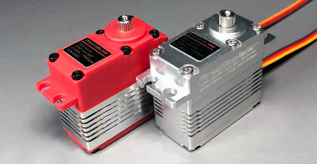
So in this servo group we take you into some of our all-alloy servos. This is how they compare when placed side-by-side with a hybrid case servo (hybrid meaning the case is comprised of both engineering polymer and aircraft aluminum).
Other stuff
- 4) 8" extensions (at receiver to mate wing)
- 2) 12" extensions - flaps
- 2) 18" extensions - ailerons
- 2) 36" extensions - elevators
- 2) B2S2600 LiIon battery pack - one each for avionics and ignition
- 1) 20A Dual Illuminated Rocker Switch (two if using electric retracts)
- 1) 5A slide switch - ignition
- 1) RCEXL Opto-Kill Switch
So as you may have noticed, while I was at it, besides making a recommendation about servos and arms, I've also mentioned what you'd want in the way of other stuff. E.g. servo arms, extensions, batteries, radio switches, plus a slide switch and an Opto-Kill.
These last two - specifically - so you have the means to shut the engine off both manually from outside the model 'and' via the radio in the event the throttle servo goes teats up. And of course, we know we make the best servos possible and we hope our throttle servo never fails but only God is perfect. For the rest of us, what General Baden-Powell wrote in the Boy Scout handbook will suffice . . . be prepared!
Extensions - details
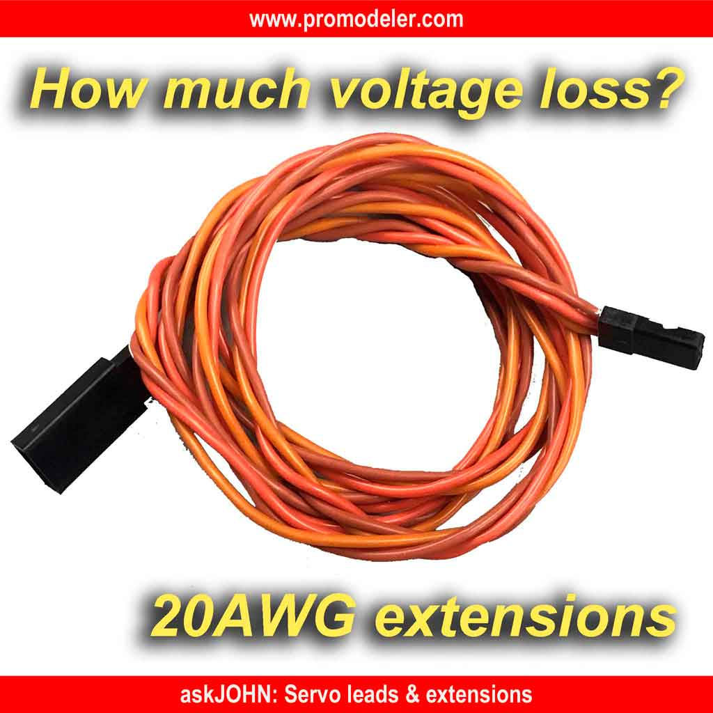
Let's touch on servo extensions. They're three-strands twisted together and made up of 20AWG wire. Basically, they're the thickest wire leads we can get crimped into the DuPont housing.
Twisted
Why twisted? To more strongly resist stray RFI (radio frequency interference). And this is a big deal. In fact, it's our advice to don't ever use flat extensions with ignition engines. Why not?
Simple, it's because 'if' the module or high tension leads begin to fail, then the ignition noise (these things are sending 40,000 volts to the plugs) basically swamps the receiver because it's act like a broadcast transmitter of pure noise. And the noise feeds straight into the receiver through the leads 'unless' they are twisted. Airplanes are expensive, right?
Anyway, you're the customer and thus, always right - but - our opinion is a few bucks saved on flat thin extensions is false economy. So heads up whether you add extensions to a servo order or get them someone else because these are basics! And it's not opinion, but physics.
Insulation
Speaking to the insulation, while there are several materials we could have select for the insulation, we opted for silicone (which is pretty much the same stuff used for fuel lines) because it's silky soft and supple, which makes it great for resisting abrasion as you pull it through wing ribs and such. Combine with high strand copper wire and you get a super flexible extension that's easier to route and doesn't get stiff when it gets cold.
Thickness
20AWG? Why such thick leads? Simple, because the thicker the wire the more it reduces voltage loss. So 20AWG is also the thickest which can be crimped into the DuPont connector. Want to know more about decisions made when using extensions, e.g. how to calculate voltage loss? This white paper discusses this, and more;
- Review to learn more: Servo Leads & Extensions
Note; these articles are free. Clicking the link opens it within a separate page.
And guys, yes I know all this info comes across as a sales pitch, but it can't be helped and it doesn't really matter where you source extensions. This because the servos only know if they're less than 20AWG, and twisted only matters if an ignition goes bonkers. Otherwise, insulation is more a matter of what's important to you.
And as far as important to us, it doesn't really much matter if you add extensions to your order, or not. Why not? It's because we live off the servos not the nit-noids! So this info is offered mostly to educate and inform what is important and watch out for.
Capacitance
Also important thing as regards extensions is how the servo works at the end of an extension. Basically, the further away from the voltage source, and the thinner the wire, the worse the servo performs. Once you have the thickest wire, the only thing left to deal with any added length from the receiver is capacitance. So let's touch on this, next.
Folks, this is important; when servo extensions exceed 30-inch in length, it's time to add capacitance. First you've heard about this?
- Review this article; Why and when to add capacitance

Servo arm details
As regards servo arms, we guide folks to aluminum servo arms for this model instead of plastic. Why? Principally due to the weight and speed of which it's capable.
Basically, we stop recommending our heavy duty polymer arms once models get into the 18-20 pound range - unless - they're relatively slow (think 30-pound Piper Cub). Same holds for heavy duty plastic servo arms offered by others. The key detail is plastic because you get to the point where the splined output shaft can strip the plastic. So because this puppy goes more like 30 pounds, we guide folks to aluminum, only, for the servo arms on the flight controls.
And in our case, not just any aluminum but 7075-T6 instead of 6061-T6 (like we use for cases and imports use for servo arms). Why is this? Simple, because 7075-T6 is a shit ton stronger than 6061-T6 (shit ton is a engineering technical term). In fact, when comparing tensile strength, the 7075-T6 at 572MPa vs 276MPa for the 6061-T6 is a touch over 100% stronger! In fact, it also exceeds the 370MPa tensile strength of mild carbon 1018 steel . . . so you get the strength of steel at the weight of aluminum!
You don't care with a 30 pound model? OK, but please remember we have folks equipping models that go 80-pounds, and more! Saying we don't play around with this and basically, there comes a point where serious engineering and material selection matters. Added to which, these are priced reasonably close to imports so if you can budget alloy arms, these are what you want.
So you really should care about the arms because there's a lot of money riding on this recommendation. Remeber, we all like squeezing a nickel until it squeals . . . right up until it costs us big time. Heads up!
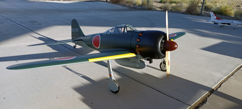
- The TopRC Models 5th scale A6M5 Zero looks nice on the flight line
So this is a typical ProModeler alloy servo arm. Eyeball how these arms feature an H-beam profile, (like an I-beam, but on it's side because of the direction in which it resists flex). Know where else you find this H-beam profile being used?
In highly stressed connecting rods of automotive racing engines . . . the ones produced by Carillo, and for the same reason!
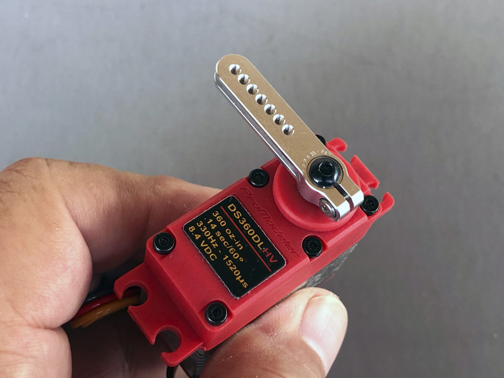
- PDRS25L-25T with backlash compensation
Best servos?
So as regards the answer to which servos are best for you and the answer being, it depends; you may be wondering, it depends on what? Very simple, it depends on how you're going to power the model, and how you plan to fly it.
By this last meaning it's one thing if you perform warbird maneuvers two mistakes high, but it's a horse of a whole other color if you fly it like you stole it down low on the deck. Especially considering this puppy goes every bit of 30 pounds (more if you just add details). Added to which, it'll hit an easy 100mph in level flight (maybe more depending on the engine). This ain't a toy!
What this means in practical terms is when you dive the model out of the sun and pull up at the end of the field and flash into a victory roll; the elevator servos, for example, are seeing some pretty serious G-loads. And at high speed, the ailerons and rudder in particular are seeing high aerodynamic loads. Loads you don't want to play around with.
Added to which, if you get in trouble and deploy flaps to slow things down at too high an airspeed, then this is why you want the extra grunt - it's needed! No, under ordinary circumstances, e.g. when everything is copacetic they're overkill but in an emergency, it's another story. Reason we're paid the big bucks is to tell you these things without sugarcoating the realities. Remember, the guy selling models wants to sell them to as many folks as possible and telling them their existing servos may not be up to the job only hurts his sales. Point being, his incentives doesn't align with yours.
So we're trying to anticipate the 'what if' about flying these things when we put together our avionics list. Saying there are subtle differences between a given set of servos and the 'right' servos for your build. Anyway, if you're unsure about the best course of action, then call us and let's chat! I promise, between us we'll suss it out. And besides . . . I always love talking airplanes!
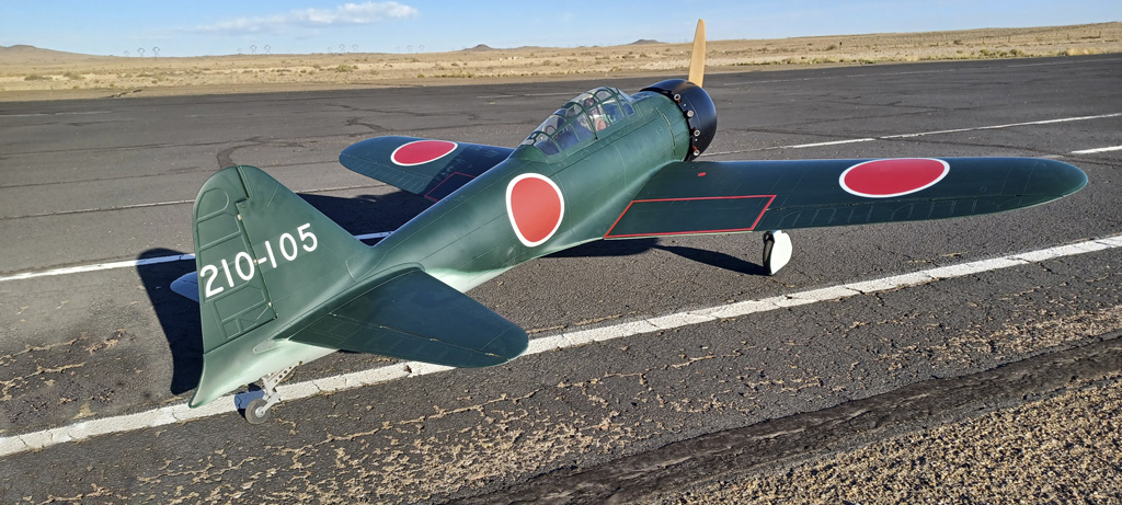
- Gorgeous backdrop of Albuquerque's Maloof Air Park
DL-series details
Anyway, Andy expressly said he was not a 'wildman' in the piloting department, so I took him at his word. However, I later noted he opted for a modification of the list of 'good' servos. Why? He went for a bit of overkill and went for a touch more torque-wise so what he ended up using were our DS360DLHV on all the flight controls.
And know this; these are the top of the range in DL-series servos. They're the one that turn more first time buyers into loyal fans than anything else we offer. This photo may help you understand why this is. And note, this is the DS180DLHV juxtaposed with the top selling Hitec 645MW. If you're curious how they compare head-to-head, this this article delves deeply into what you get for your money;
- Learn more; Hitec D645MW vs DS180DLHV
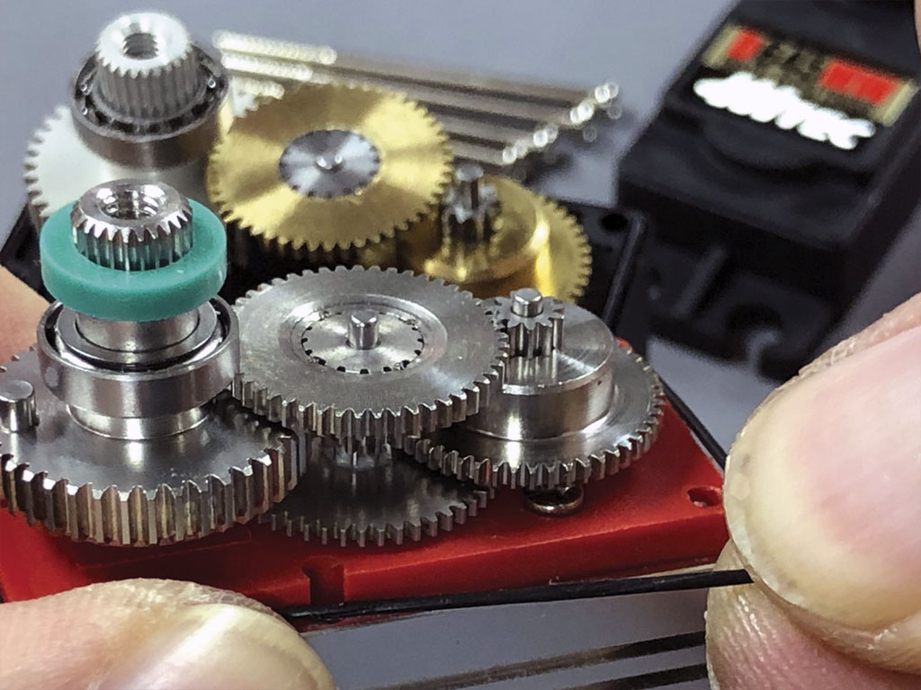
- ProModeler DL-series DS180DLHV servo juxtaposed with a Hitec D645MW
So now let's dip our toes into the TopRC Model 1/5th scale A6M5 Zero build. First up, let's look at the elevator servo installation.
Elevator servo installation
All in all, this is a pretty slick set up. Basically, they bury the servos within the root end of each horizontal stab. All you do is slip them in place through the root rib and secure it with mounting screws. We make it a bit easier because you get Allen head mounting screws with your servos instead of el cheapo Phillips like everyone else supplies.
I bring it up because details count, right?
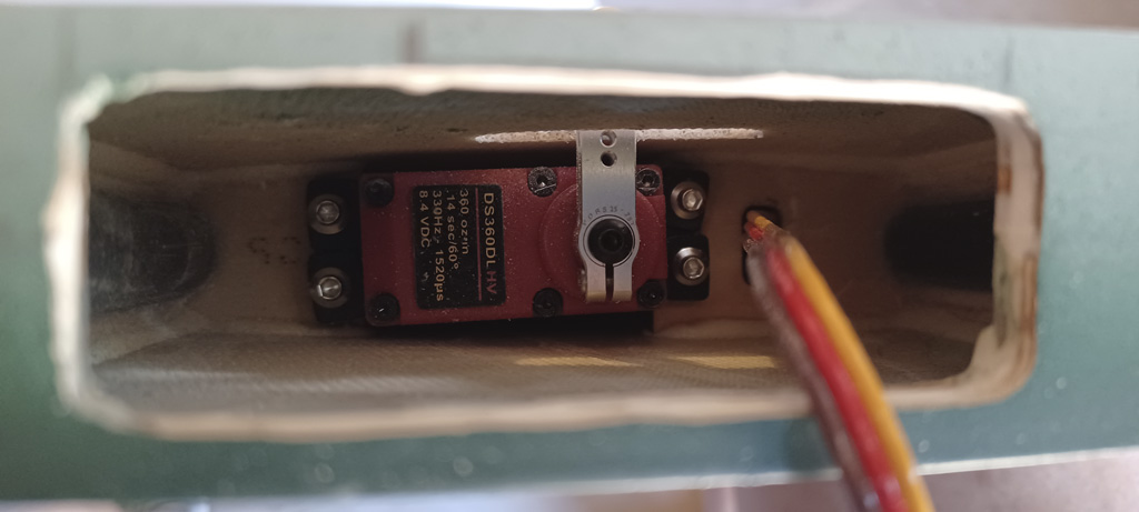
- Elevator servo mounted within the horizontal stab and fitted with PDRS25L-25T
The build includes a very nice pushrod with ball ends to actuate the elevator!
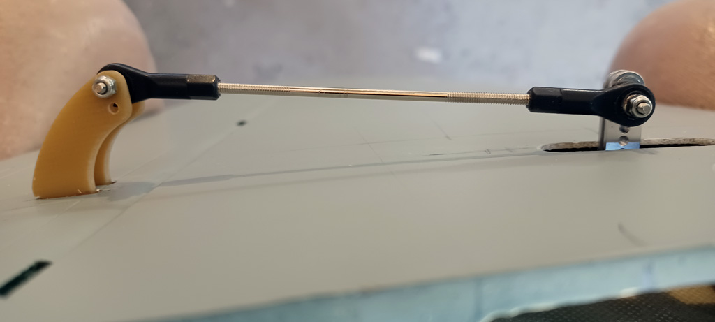
- Ball link pushrod for each surface is a nice touch
Servo arm - dimensions
So let's eyeball how these linkages are assembled. They're using M2 hardware (means 2mm threads).
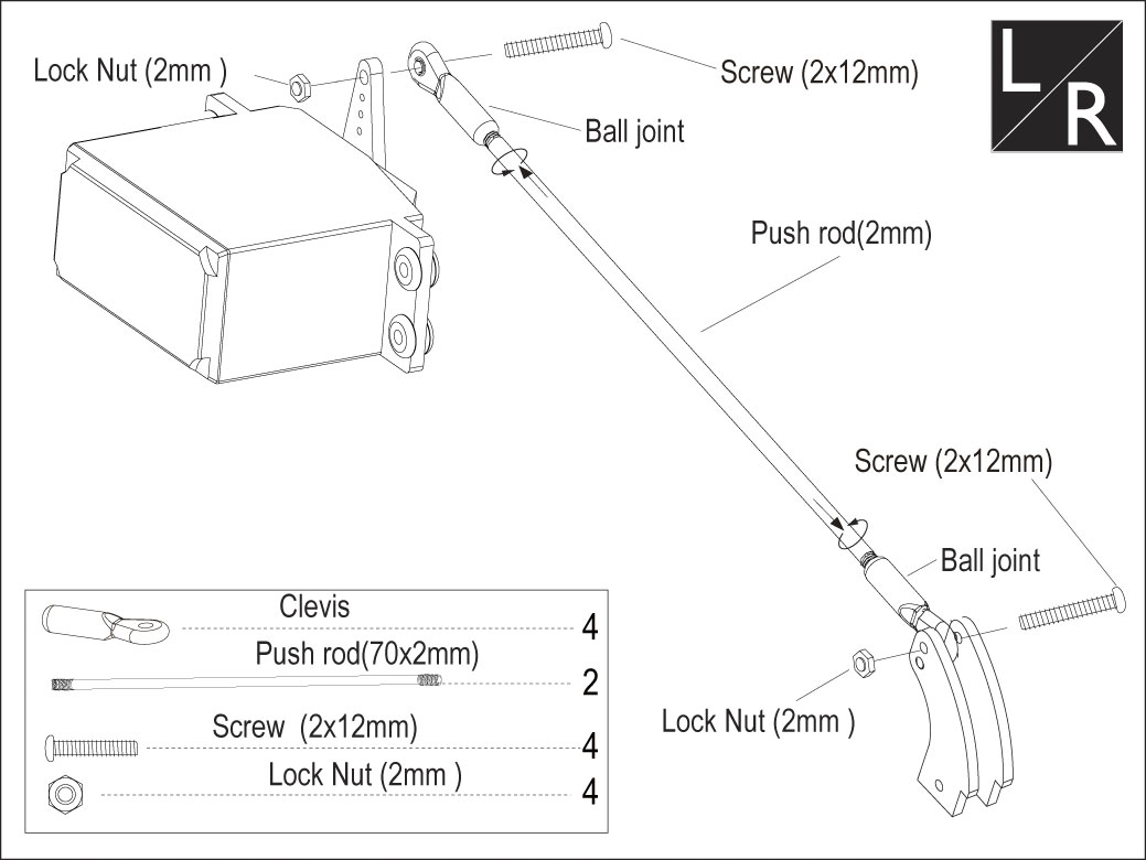
So we offer 5 different aluminum servo arms threaded M2.
No need for a decoder ring, the first number after PDRS is the length to the furthest mounting position. And the -25T refers to the 25-tooth spline of the output shaft.
- 15mm - PDRS15-25T
- 20mm - PDRS20-25T
- 20mm - PDRS20U-25T (U means underslung - ball goes between arm and top of the case)
- 25mm - PDRS25L-25T (L distinguishes it from the 3mm PDRS25-25T - no 'L')
- 32mm - PDRS32-25T
Note; the arm is equipped with an Allen head backlash compensation screw, and mounting positions are on 2.5mm centers.

- PDRS25L-25T with 7-mounting positions on 2.5mm centers
Rudder servo installation
So the instruction manual for the rudder servo calls for a double horn servo arm, and that's what he used.Thing is, these are really meant for ganging servos, not for cables even though that's what modelers are using them for. The right tool for the job is actually a pulley. More in a bit.

- While that's not our horn, our PDRS40D-25T will do the trick nicely
Note; the link in the caption above goes to our similar double-horn servo arm. Ours are milled of 7075-T6 instead of 6061-T6 (bit more costly but much stronger) and has an H-beam profile. Both so the arm is significantly stiffer under load.
And yes, you can use this tiler-type servo arm for the model, but . . .
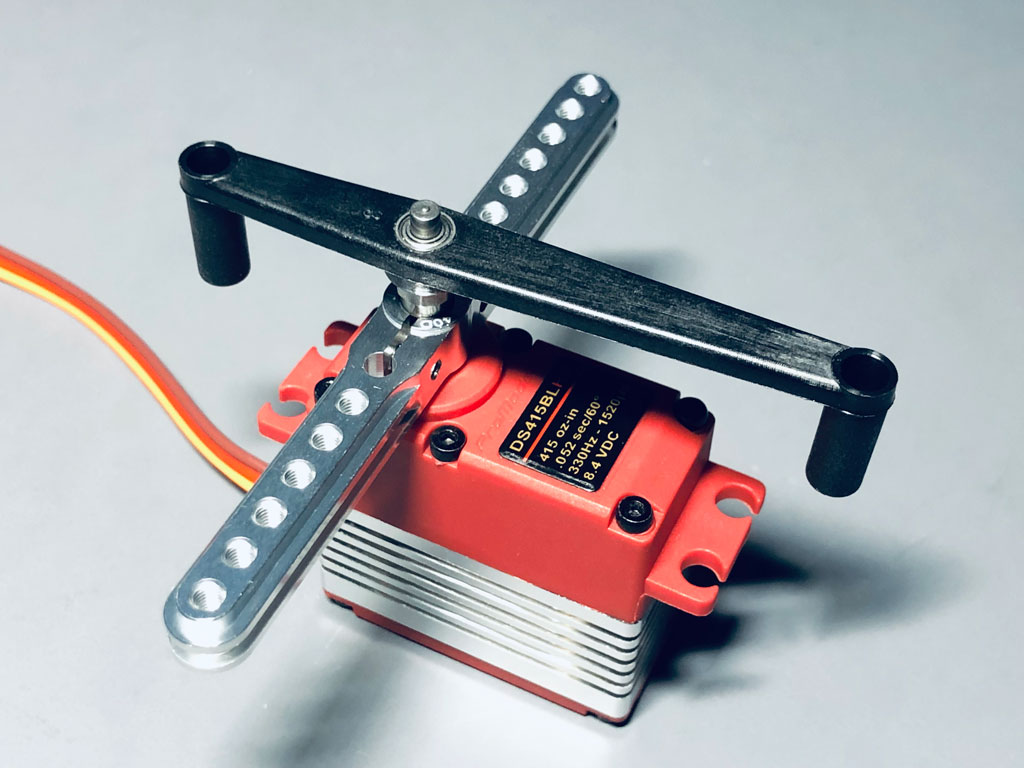
- The longitudinal output shaft stabilizer prevents lost motion under load
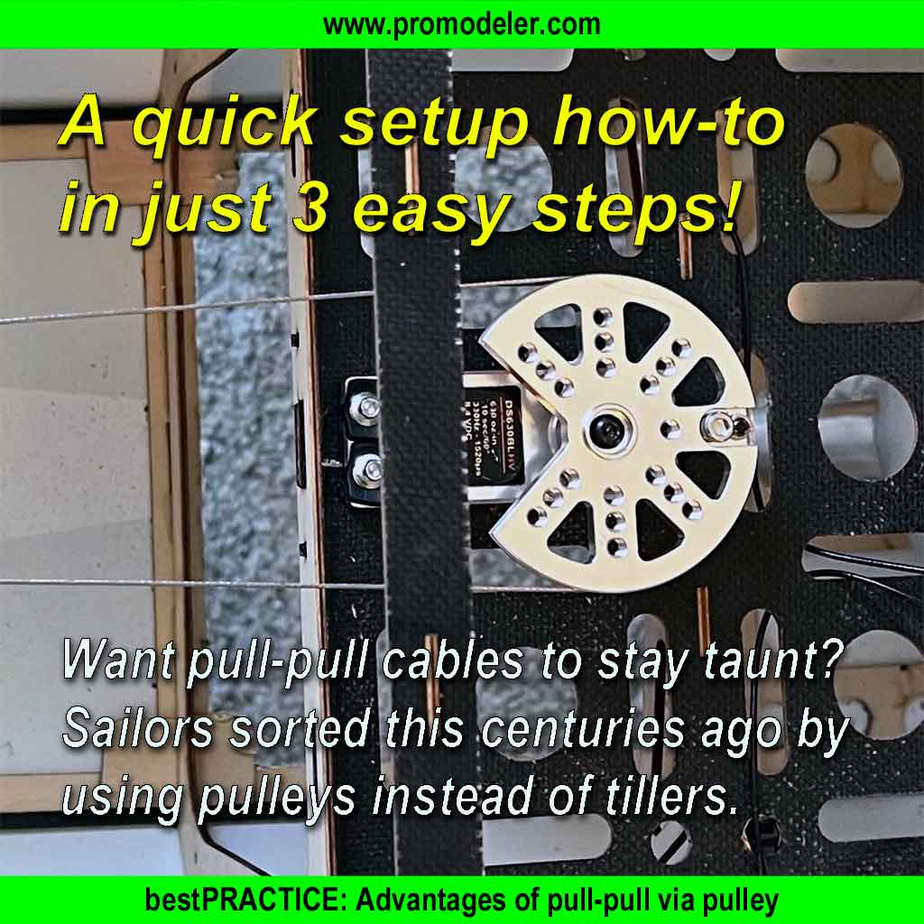
. . . while they work OK, quite honestly, I prefer to use a pulley for the job, instead.
So to learn a bit more about why, review this article, and note; the additional threaded holes also allowing hookup of the tail wheel cables - just as with a tiller.
- Why a pulley beats a tiller: Advantages of pull-pull via pulley
So while we're doing flying surfaces, let's continue by eyeballing the underside of the wing and see the detail for the aileron and flap servo installations.
Wings
So here's a tip; Andy is a savvy guy and once he had his ARF in hand, because he was unhappy with the alminum wing tubes he went online and bought carbon fiber replacements. Benfit? Saved 15.8-ounces and gained strength. Found them from the usual online suspects using these as the search terms;
- 600MM Length Carbon Fiber Tube 30x27x600MM,10/12/16/22/25/35MM Available, 3K Roll Wrapped Twill Matte Finish
- 420MM Length Carbon Fiber tube 18mm x 20mm x 420mm - Glossy 3K Twill Weave Wrapped, 100% Pure Round Tubing
Servo installation
The four servos in the wing are mounted on hatches. This is both straightforward and hands down my favorite way of installing servos in flying surfaces. In fact, if I had any pull with TopRC Model, I'd suggest they mount the elevator servos this way, also (but nobody in China asks me Jack).
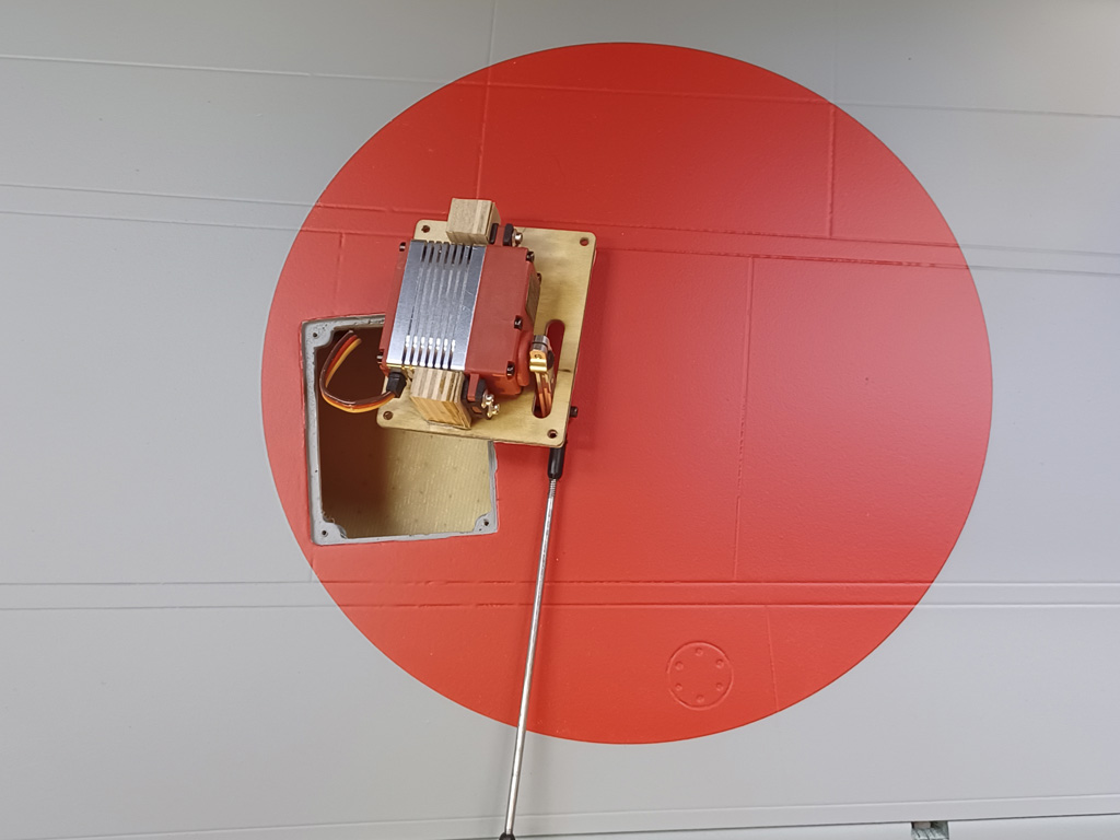
- Aileron servo nicely mounted on the side of a plywood hatch
So kindly allow me to shill another product. If you look at how they recommend mounting the servos to the plywood covers you'll note Andy didn't trust those, either. He made up plywood blocks and this definitely works. But if you would like to see what we offer in this regard, our sidemounts are available in four sizes. This is the standard with a standard servo installed (duh).
Note; even the mounting holes are tapped. It's because we also supply this with flat head machine screws, too so the finish surface isn't ugly. Later, a drop of color-matched latex paint makes them disappear! Your local Lowe's or Ace Hardware will do you a small sample size container for just a couple bucks.

- Sidemount supplied with Allen head hardware
Anyway, once your servo is secured to the hatch, then four small screws at the corners, then all that protrudes is the end of the servo horn and the linkage rod to the control horn.
It's a nice and clean setup! Like I said, my favorite. Enough so I've retrofitted pocket-style installs with this method.
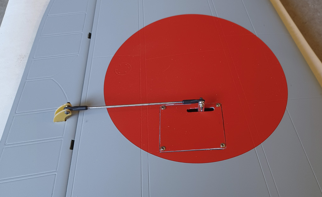
- Flush mounted within the wing panel's underside
So in this next photo we get a gander at the flap servo linkage. Reason I'm including it is just to marvel at the detail work TopRC Model go to with this thing.
Like all these panel lines and rivets are just an airbrush loaded with watery black plus a soft pencil away from becoming smudged and more realistic for that war weary look these things accumulated after a few sorties. This one is clean and shiny just because it's new.

The flap servo is mounted similarly, note the panel and rivet detail
So here we have the wing surface, once it's all buttoned up and clean as a whistle. Best part of side mounting the servos with the output shaft parallel to the hinge line is the servo pushrod doesn't transit side-to-side as it does with a pocket style installation.
Note; landing gear wheel cover not yet installed. It's coming.
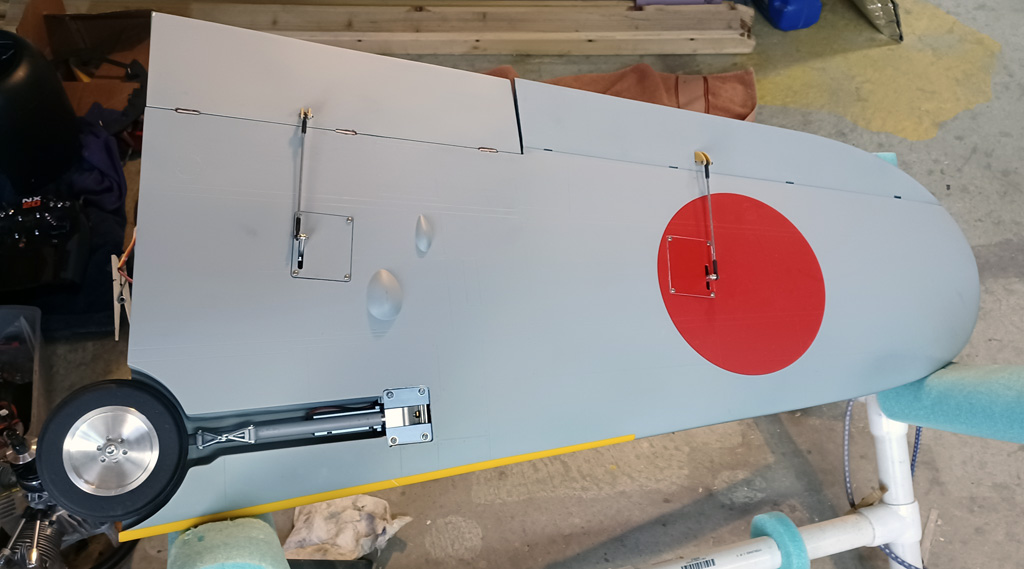
- Clean lines shows off the normally not seen surface detail
While we're dealing with the under side of the wings, let's eyeball another detail on the underside of the model, the drop tank.
Aux fuel drop tank
A nice detail included with this model is the drop tank. The installation relies on preinstalled M3 blind nuts and 15mm long machine thread bolts. Problem is, the darn thing gets in your way!
So Andy came up with this nifty method that relies on a pair of magnet from K&J Magnetics to secure it in place. They are countersunk for a screw head. Anyway, the hook part is from a scrap piece of Delrin, and the neodymium magnets are also readily available online form the usual sources but look for the ones that use a screw to fix in place.
He used one on the belly plus another at the tank. And while they are rated at 24-pounds, he actually measured the pull at the end of the tank at 10-pounds-force to detach. Anyway, removing it is duck soup, just tilt forward and once the magnet breaks loose, then slip it off the hook. Easy peasy!
Anyway, the whole thing is very nicely executed and I, for one, am very glad he shared this trick with us.

- Nifty detail, the drop tank
And by the way, if you feel like engaging in a bit of modeling, we offer a special servo horn made for things like drop tanks. It's our part numbers PDRS195L-25T and PDRS195R-25T (for left and right, depending on what suits you better).

- PDRS195L-25T mounted to a standard class DS90DLHV servo
ProTip: if you like how the servo lead is coiled in the above photo, it's easy. All you do is wrap the lead around a screw driver shaft and heat lightly with the open flame of a lighter. Or use a heat gun. Either works. Then allow it to cool and Bob's your uncle!
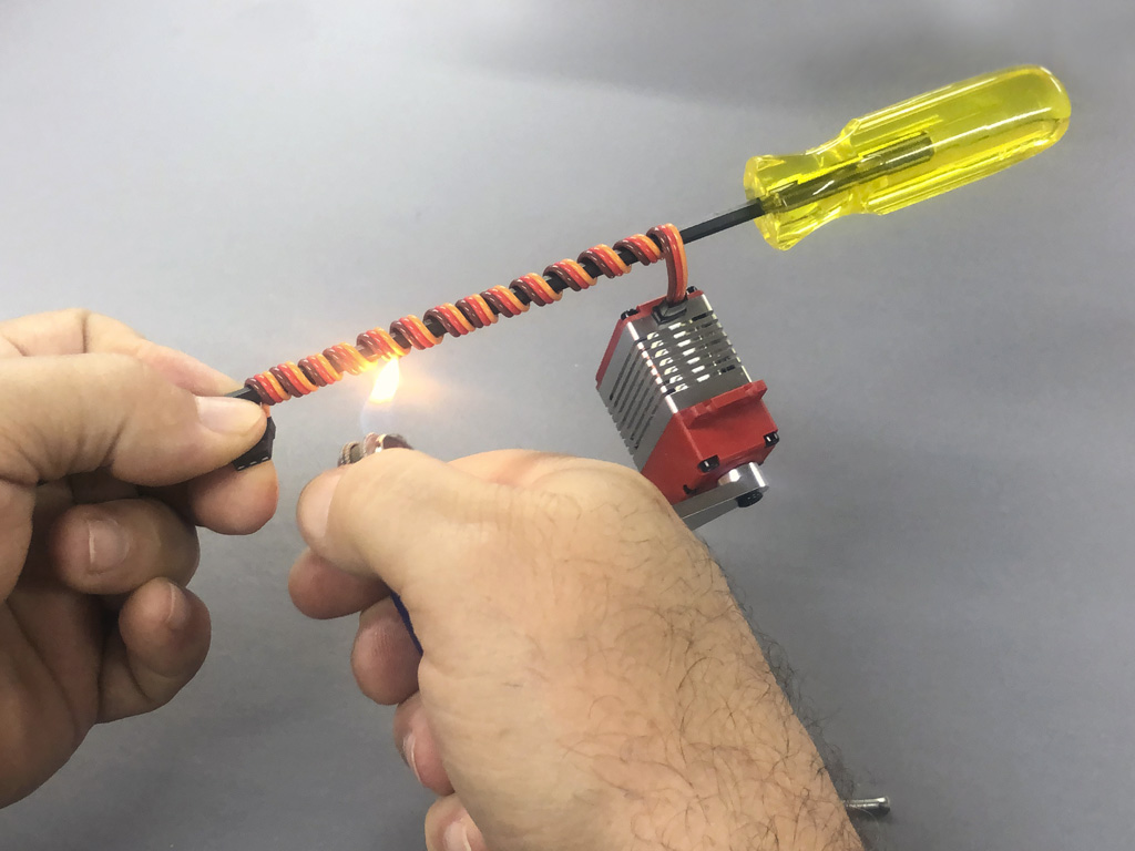
- A bit of heat on the jacket and it'll hold a new shape
So next let's delve into the inside of the fuselage to see how the throttle and inner gear door servos are installed. We'll also get a chance to see a nifty avionics switch installation.
Fuselage - servo installation
When you get the model, the fuselage interior at the wing saddle area is positively cavernous! We already touched on the rudder servo install, now let's see the other three servos, the two for the inner gear doors and the throttle. And a drop tank if you get ambitious (and if anybody does it, kindly share photos).
Andy reports the plywood is well attached with nice fillets between plywood and fiberglass sides. The use of triangle stock is strategically applied to the tank floor as reinforcement.
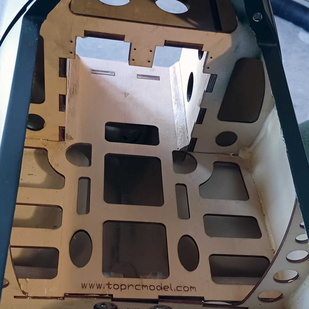
- Plywood bonded to the fiberglass fuselage
One of the first steps is installing the servos for the throttle and gear inner doors. However, before this, Andy glued up the plywood mount for the throttle servo.

- Plywood box structure holds the thottle servo
In this next photo, Andy got a good angle to show the installation of the two servos for controlling the inner gear doors.

- Three servos mouted near leading edge, throttle and both gear doors
And here you get a pretty good look at how the pushrods actuate the hinged inner gear doors. It's a straight shot!
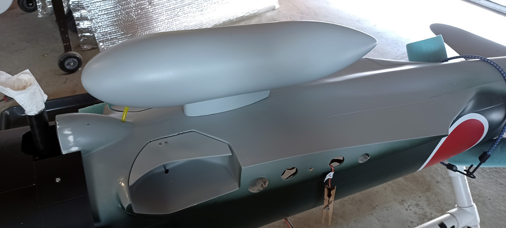
- Inner gear door push rod is juuuust visible
And in this next photo, you get a good look at the linkage, which is just a straight rod. It really doesn't get easier.
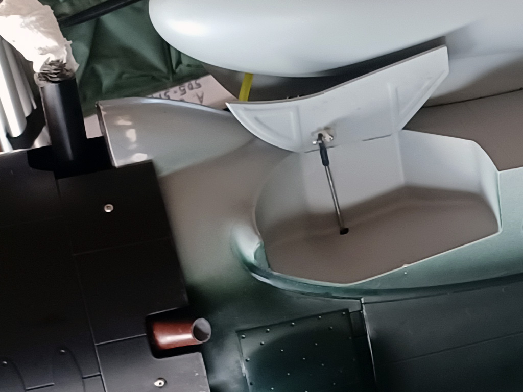
- Inner gear doors are servo operated via this linkage
This next photo shows how everything is packed in. This is the final equipment installation photo as the fuel tank is installed and strapped down securely with Velcro. It's also reverse plumbed. This to keep lines from being pinched against the firewall. When we get to the canopy and pilot figure you'll better understand the reason for the packaging Andy has done.
So back to the fuel tank, and added advantage of the reverse is nose down for landing gives you max possible fuel. Downside is a go around pitches nose up and does the opposite. As in all things in life, you accept the good with the bad. Anyway, forewarned is forearmed!
Note; both battery packs are installed (one for receiver and servos, plus another for ignition and retracts). As are the switches.
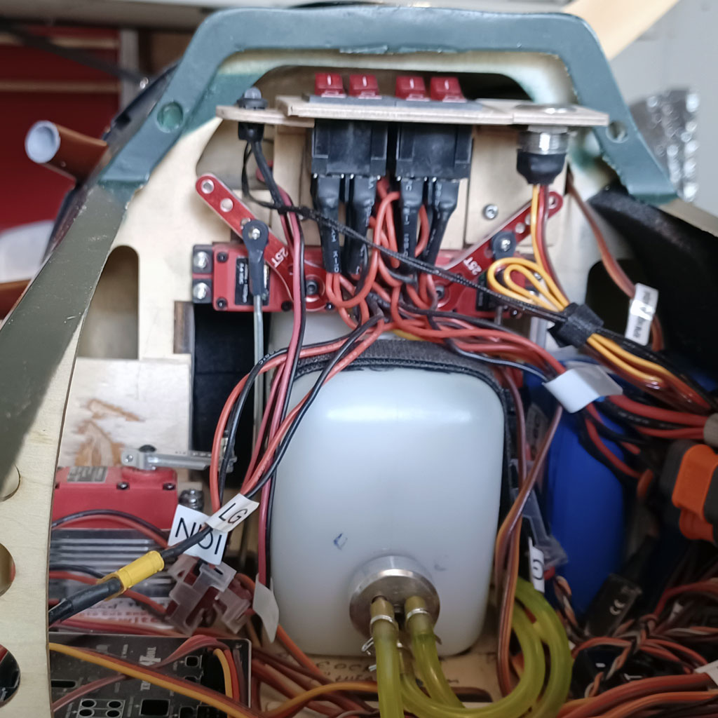
- Final equipment installation, note paint in the exhaust outlet
We also get a look at where he installed the RCEXL Opto-Kill switch. Also the throttle servo with pushrod.

- Throttle servo with linkage and Opto-Kill
So I mentioned batteries. He used ours which come with dual leads. This lets you connect it to the receiver in two places instead of one. And if you think it through, then this implies using two on/off switches for redundancy.
Here's the major point; like the argument isn't to use two batteries but to use two switches! Why? Simple, it because the batteries themselves are inherently reliable. But people engaged in the fear trade sure want you to think so. The fear trade?
Note; make the second connection anywhere because receivers use a bus power distribution structure.
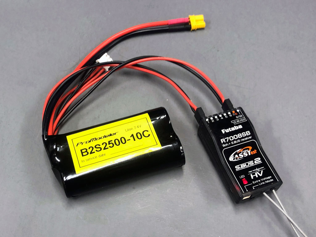
- Using a battery with two leads gives several advantages
Saying if batteries weren't reliable, then models would be crashing left and right, e.g. all the damned time due to faulty batteries!
But they aren't crashing regularly. Like yes, we've all heard the story of the guy who had a failed battery - but - I'd bet you a doughnut it was a operator error so what actually failed was either the guy who forgot to charge the darn thing, or had to get one more flight and flew until the pack was dead. Like that's not battery failure!
Further along these lines, if you reason this through further, if batteries were unreliable, then emergency vehicles like ambulances (as well as police cars) would be equipped with two batteries instead of one. They aren't . . . for good reason. Major point being, vendors selling the concept of 'safety' by using two batteries are engage in what in business school is taught as the 'fear trade'. Same business as the insurance salesman who persuades the wife of a 25 y/o to pony up for a policy when the same money into VOO would compound nicely by the time they are ready for retirement.
Everything comes down to odds (what built Las Vegas) and taking advantage of folks who never learned how to calculate odds is called the fear trade. It's literally taught in business school in college! Saying they're selling snake oil to folks who never took statistics because modelers are afraid of crashing and buy into the notion two batteries are better than one. They're mistaken.
Us? Of course, if you just want to give us more money, then we're delighted to sell you a 2nd battery (after all, a) we are in business and b) not stupid) but seriously, you only need one battery. That, and toting the dead weight of a second pack reduces performance.
Anyway, it's something 'I' never do unless I'm also toting a 2nd receiver! Yes, sometimes I'll use two receivers with a model. And when I do, then I have a second pack onboard. Never heard of this?
- Learn more by reviewing this information; Receiver power for 33% and 42% aircraft

Switches
Saying what you really benefit from, however, is having two switches! So because I've raised the subject of two switches. You can use ordinary 5A slide switches.
And we offer the best in the business. These are genuine Japanese Nobel with shielding against stray RFI (the folded metal bit under wrapping the body).
Moreover, unlike hobby-grade switches, we go the extra mile of using potting compound (applied to the solder terminals). The basic idea of this is just as in full scale aviation, to help protect against vibration because solder fractures. When we tested hobby-grade servos we found vibration failure almost 100% of the time.
Bottom line? Potting compound is important for this switch type.
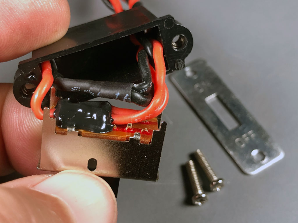
- Potting compound greatly aids vibration resistance
Dual switches
So why two switches? The reason for this is simple, when you have two switches in parallel you gain two things. First, the current flow through any one switch is 1/2 the total. This reduces heat.
But also, and this is the most important in our view, with two switches in parallel, it means odds of both switches failing on the same flight are astronomical. Like it's the cheapest crash insurance you can buy!
Dual illuminated rocker switches
So we offer a dual switch assembly. Dual meaning two totally independent rocker switches sharing a common plastic mount. Besides this one equipped with DuPont connectors, we offer the same switch assembly but with XT30 and EC3 connectors.
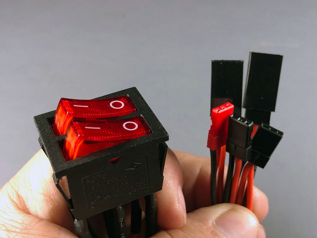
So here's the deal with this switch assembly. it's fairly large. Best way to mount it is within the structure, where it's accessible. So what Andy did is to mount two. One routes the power from one battery pack through to the receiver. And because he's using electric-powered retracts, he used the 2nd lead off the ignition battery (remember, or packs come with more than one lead) to power them!
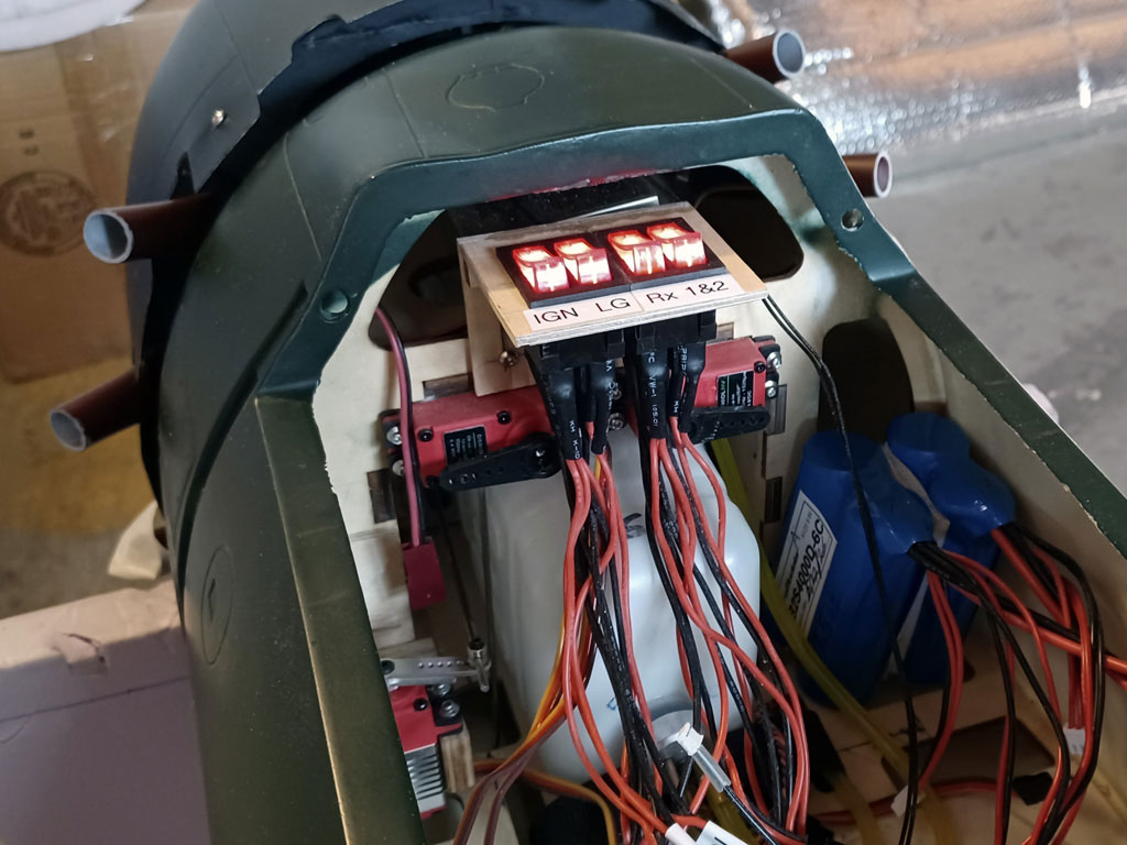
But enough yap-yap about switches. Let's get back to the build. Up next are the retracts!
Retracts
So Andy had Robart retracts on hand from before they closed the doors. Electric units instead of pneumatic. So this isn't rocket science but the gear legs were naked until he installed the uper gear doors. For this he machined Delrin blocks.
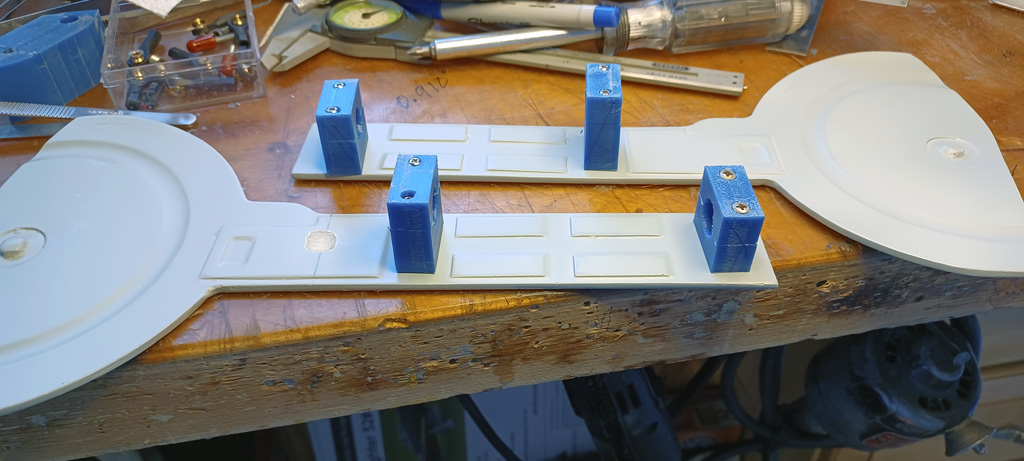
- Delrin blocks to stand the door off the leg
Once installed, the appearance of the model gets kicked up a notch, doesn't it?
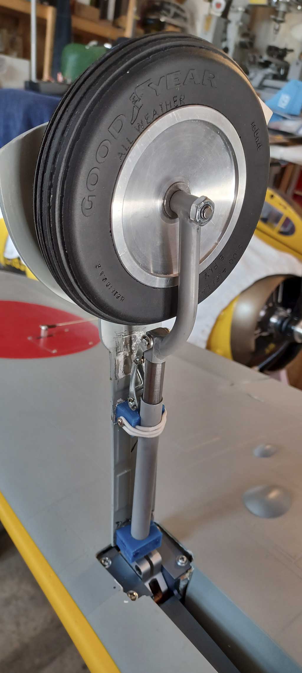
- Gear doors add something special - note use of breakway bands
Last thing about the retracts, since you can't see it while installed, Andy shared this photo of the tail gear retract unit. Pretty sweet, isn't it?
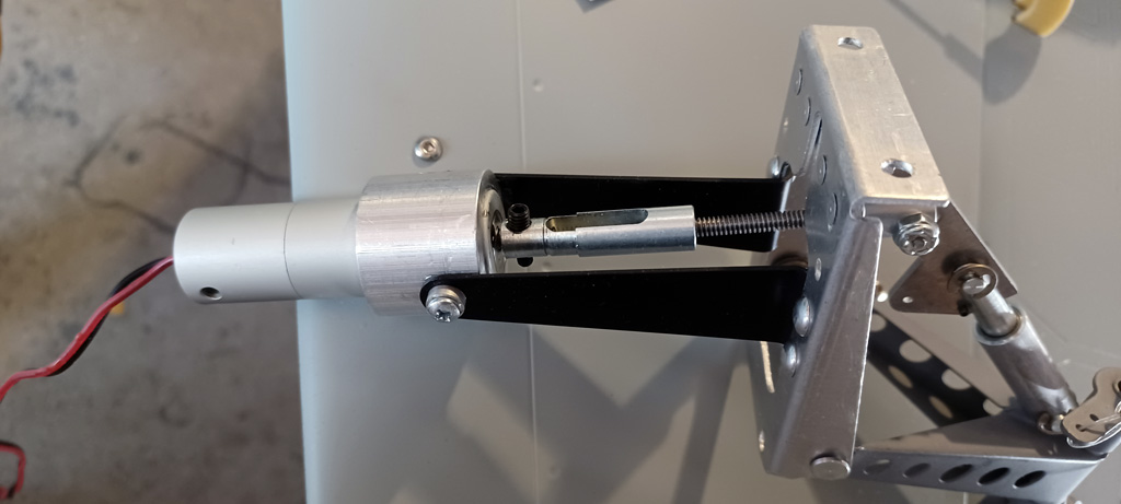
- Close up photo of electric tail gear
And this brings us to the engine installation. The Saito FG-90R3, a gorgeous 4-stroke with a fantastic rumpy-rump at idle reminiscent of a Harley! Next, we're going to touch on the installation.
Engine installation
So the engine Andy wanted to use required a bit of modification of the existing firewall. Could he have left well enough alone?
Yes, but he said it meant the carburetor sticking inside about 2-inches. He preferred (and I concur) for the carb not be within the fuselage. After all, these things spit up fuel during part throttle operation!
Anyway, he shared a few photos of the job, beginning with this one after he paused part way through cutting the existing engine box, expressly to snap this photo.
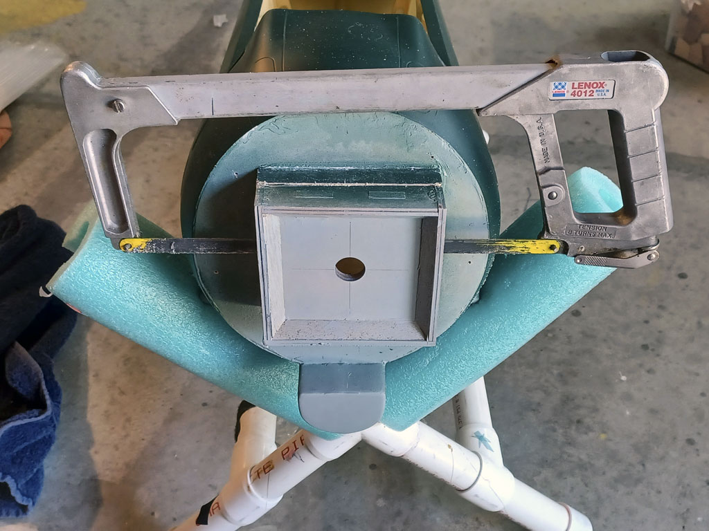
- Yes, a hacksaw will do the job
So this is what you end up with, a bit of existing engine box to throw away. Well, not really.
What actually happens is he'll salvage some of this to re-use, but we're getting ahead of ourselves.
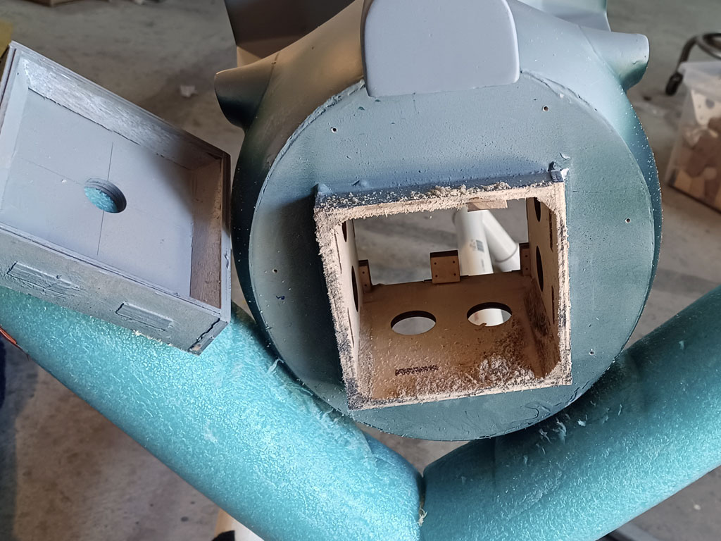
- Existing firewall as removed
Next is the cowl ring. This is supplied with the seven exhaust stubs and screws to the airframe.
ProTip: use CA on the wood where the screws thread in to help keep them from vibrating loose.
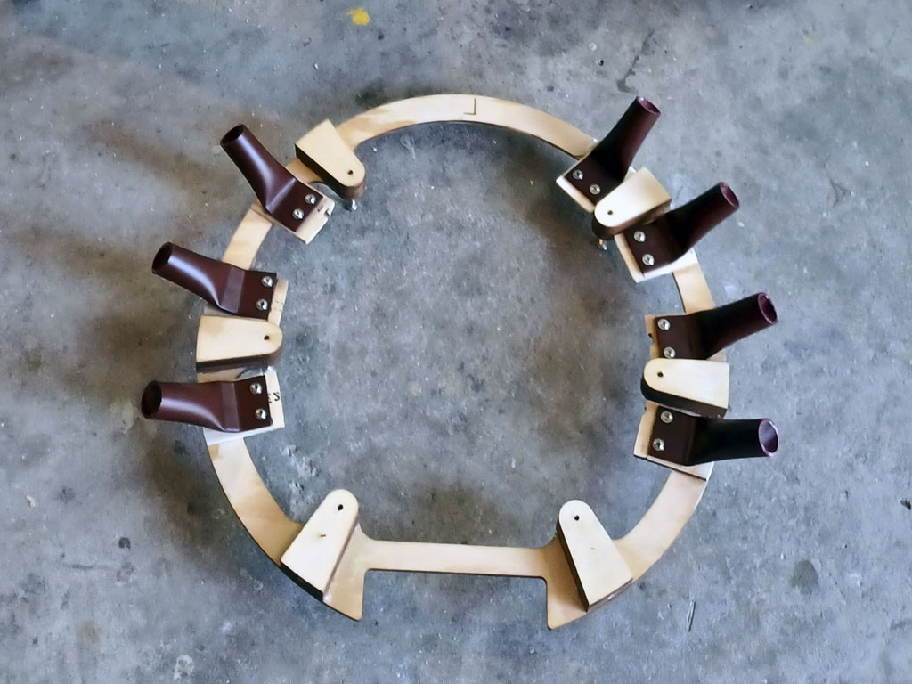
- Cowl ring with exhaust stubs
So in this next photo, the cowl ring is being dry fit to the firewall. Just a few screws hold it in place. But as Andy explains, better to find all the gotchas now, before you paint yourself into a corner. Makes good sense to me!
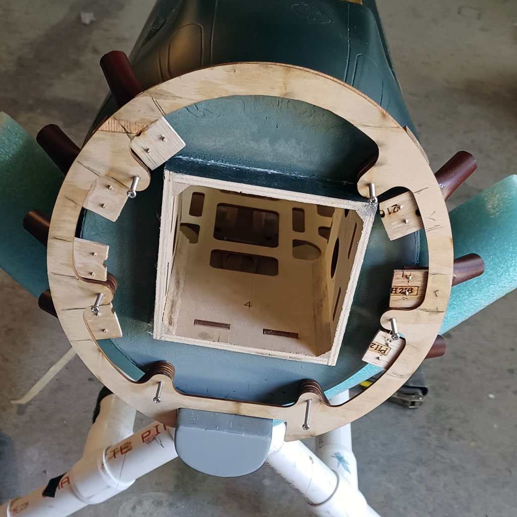
- Cowl ring temporarily mounted in place
Now we have a good look at how Andy reused the remnant, the piece he cut off. Basically, all he did was cut off the plywood surrounding the original the firewall. He even salvaged the triangle stock!
Then following careful alignment, he epoxied it back into place - but - not before he doubled the thickess. Important as the radial weighs more than the typical gasser. Recycling at its best!
Anyway, a healthy smear of epoxy and Prather microballons and it's now stronger than it was originally!

- Original firewall epoxied back in place
And now for a look at the cowl temporarily installed.
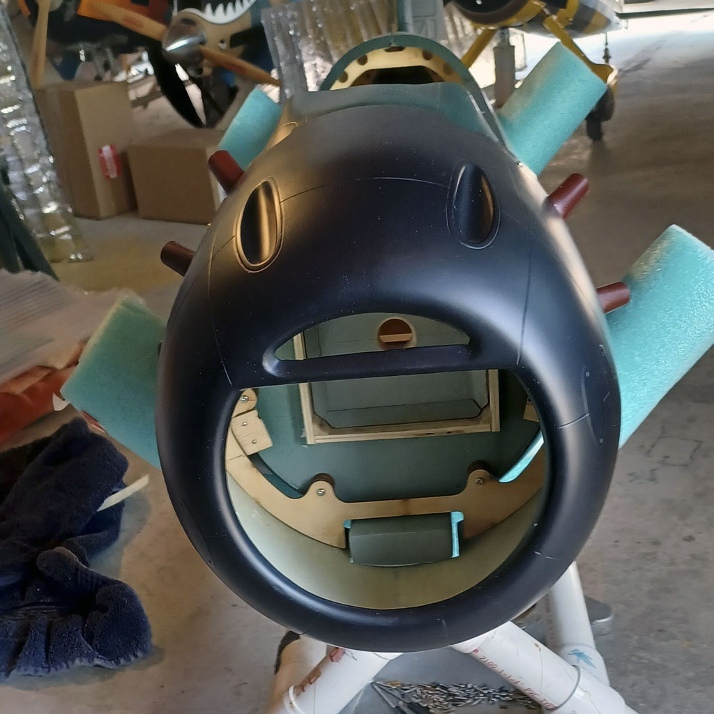
- Temp install of the fiberglass cowl with exhaust stubs
And with this photo we get a look at the fit between the cowl and the simulated exhaust stubs.
This presents an opportunity to make slight adjustments for best clearance.
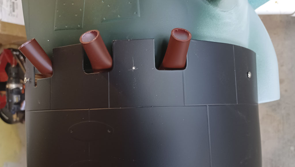
- As supplied exhaust stubs
So in this photo we see the aluminum standoffs to obtain the clearance between prop and cowl Andy was going for. Note how he inset if a touch to get the prop in the proper position. By the way, these aren't store bought aluminum standoffs. Instead, he machined them from bar stock himself.
Note; they're 3/4-inch diameter to provide more bearing area to handle the load where they meet the plywood. Nice touch, eh?
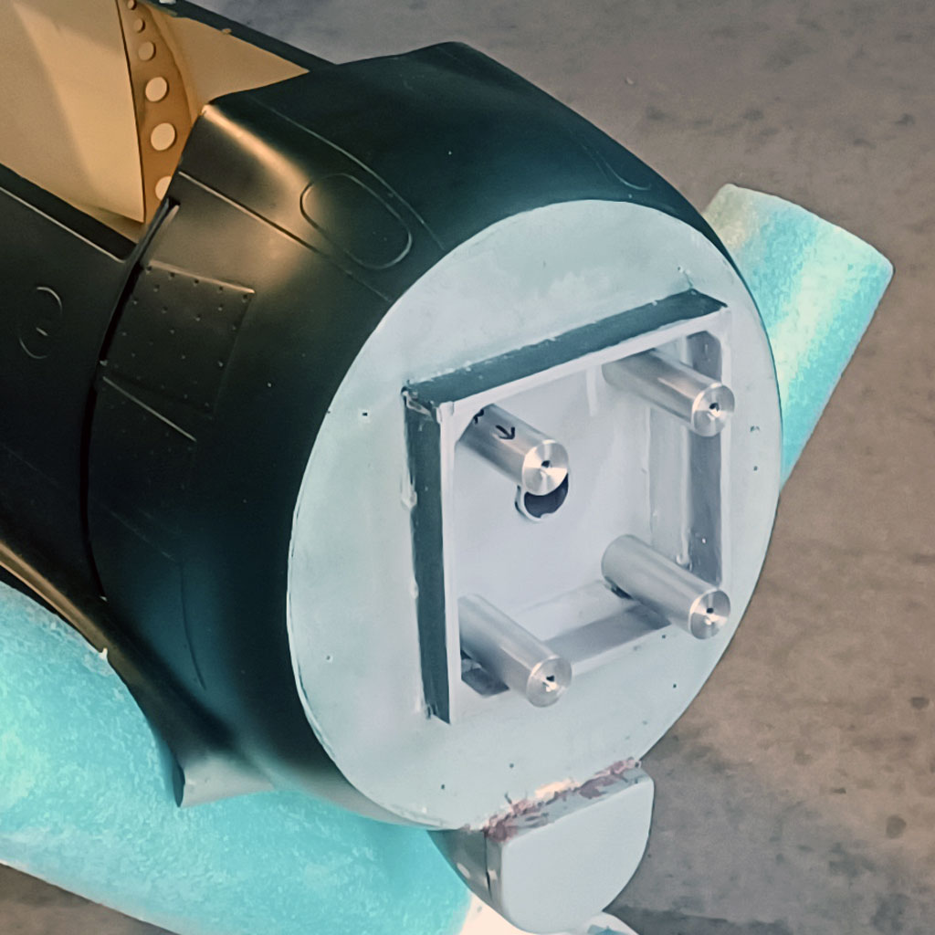
- Aluminum engine standoffs installed on the now painted firewall
And finally, the money shot, the Saito FG-90R3 engine in all its glory! Is this beast gorgeous, or is it just me?
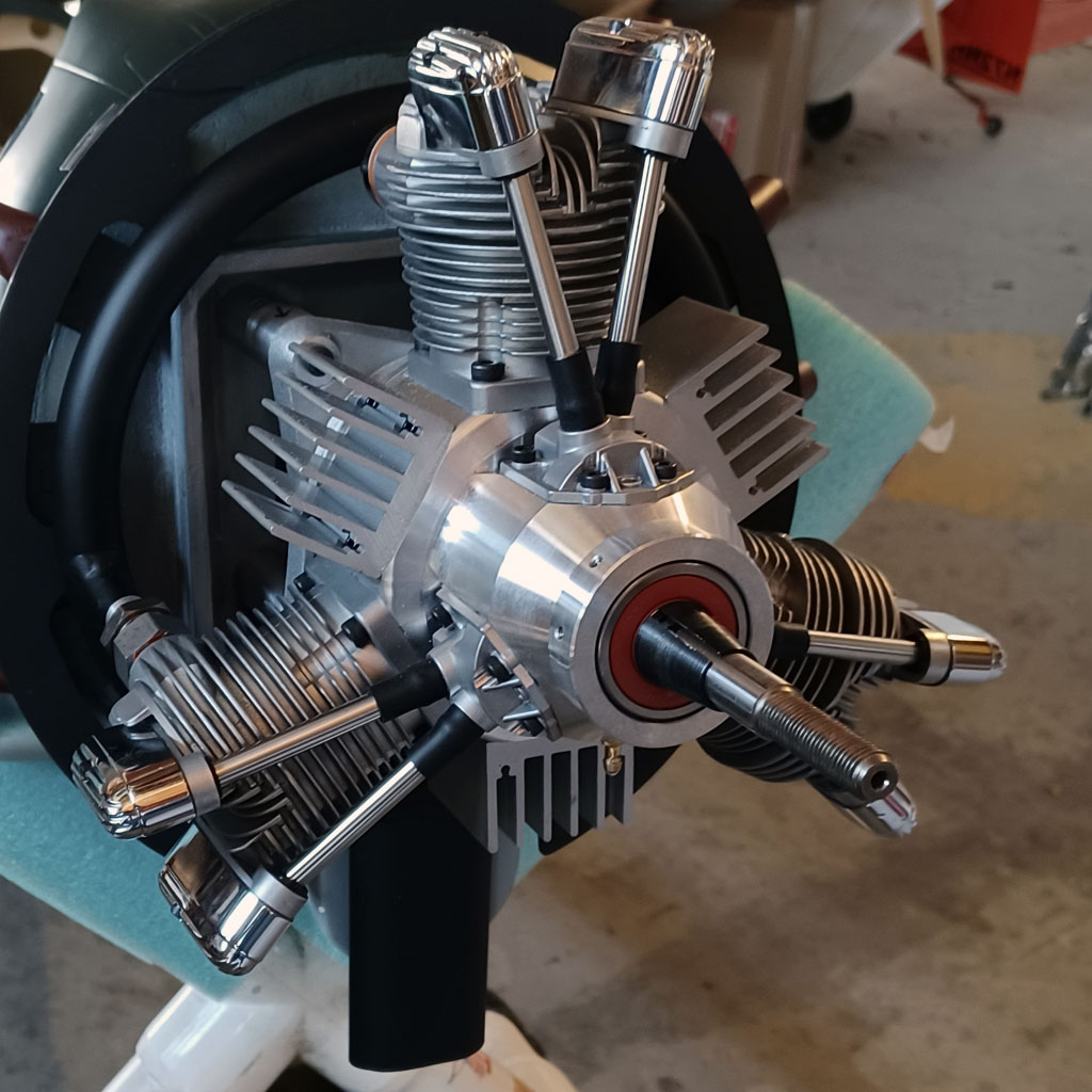
- Superb Saito radial, the well regarded FG-90R3
This next photo is important. When an engine is cowled in, air has to move through the cooling fins.
You cannot simply assume the prop will blow enough air on them to cool the engine. So this bit of plywood is designed to force air through the fins instead of allowing it to free flow around them.
Notches are also there for better air flow through the aux heat sinks the factory installs to the crankcase.
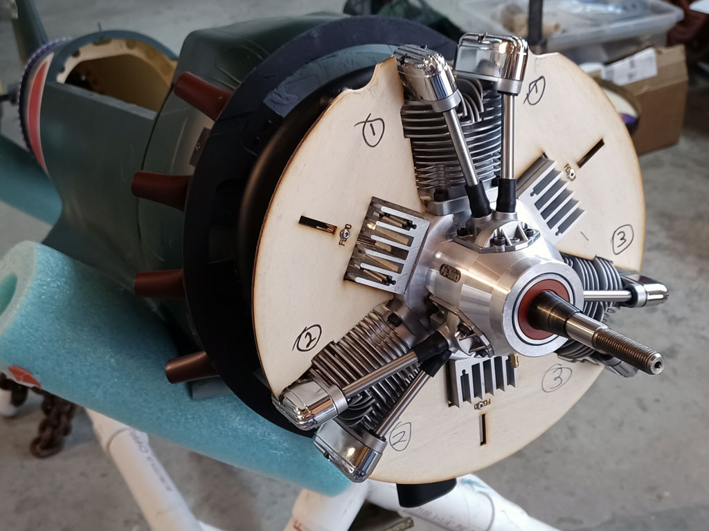
- Cooling air in the form of plywood forcing air through the fins
And after a bit of black paint to protect the wood and hide it, the final installation.
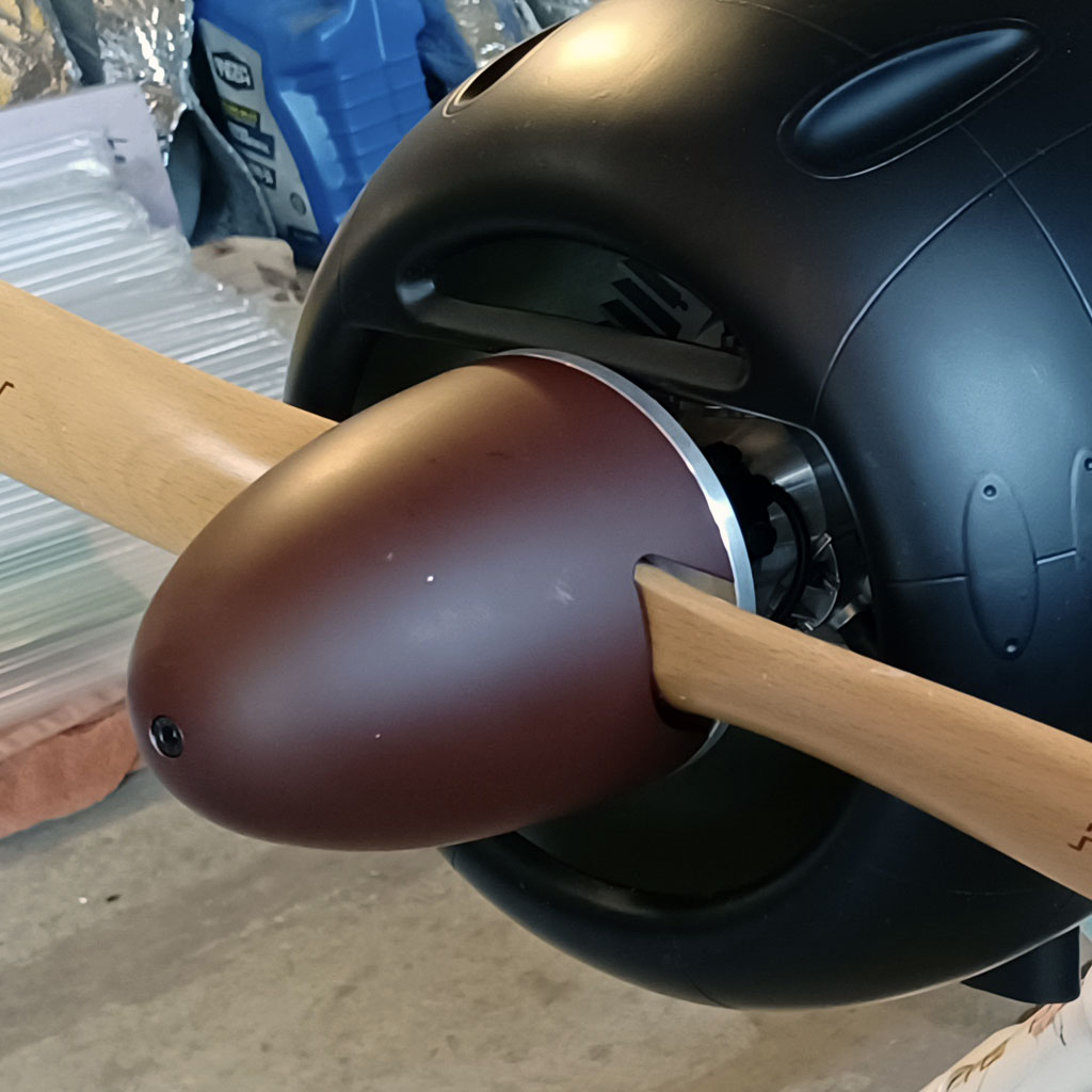
- Saito FG-90R3 with prop and spinner installed
Cockpit and canopy
So the model gets a pilot figure because nothing looks worse than an aircraft flying along with nobody at the controls. After all, psychologists will say we're nobbut boys with big toys reliving childhood. That, or Walter Mitty letting the imagination run wild.
Me? I say screw the psychobabble and chose to believe we fly for fun. That, and the whole reason for flying scale models is to replicate the full scale experience as close as we can. Thus, I hold the belief no-pilot cockpits look Mickey Mouse!
By the way, the pilot figure is by Warbird Pilots and it's a 1/5 scale product (12-inches tall). Moreover, in case you're unaware, these bodies are actually separate items of clothing assembled on a wire frame with cotton forming the 'bulk' of the body figure. They weigh about 5-ounces.
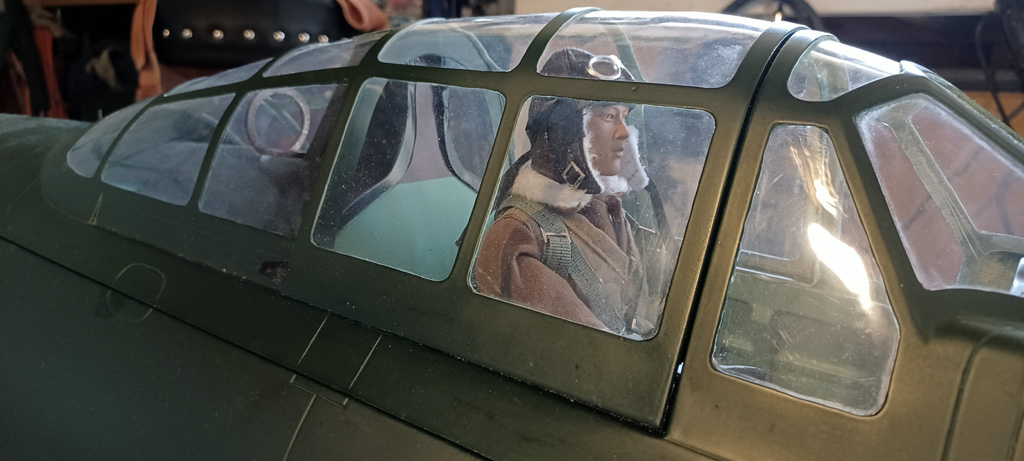
- TopRC Models 5th scale A6M5 Zero cockpit complete with pilot figure
Nice thing is this; due to the wire frame, you can bend it into whatever pose best suits you. Point being, if you ever observe a pilot within the cockpit, he's not sitting at attention (like the typical figure). So if you want to add a bit of a hunch in his spine, then this method of making the figure lets you add the subtle curve yourself.
End result? You get a custom, more life-like, pose!
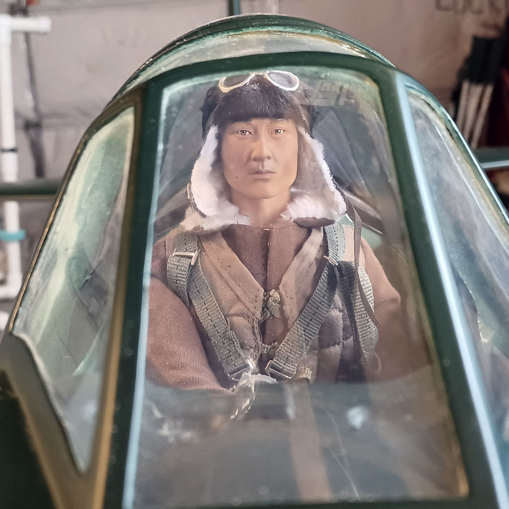
- Warbird Pilots WWII Japanese figure is 12" tall - eyeball the seat belt straps
Earlier I mentioned how Andy packaged the avionics in the fuselage. It's to do with the cockpit and pilot figure, which take up a significant amount of volume.
In this photo you can see he went full Monty, so it's the whole figure, body and legs included instead of just the torso.
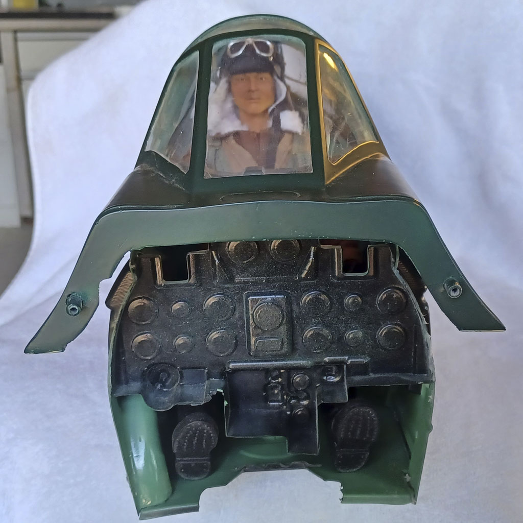
- The feet are just peeking out
And in this side-view you can better appreciate the amount of space required to pull this off. I feel TopRC Model are to be congratulated for paying attention to the details.
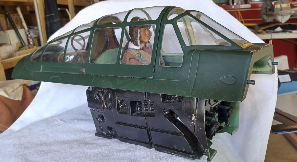
- A significant amount of space is required for the cockpit
Last cockpit photo. Look how he cut the windscreen for access, used Velcro strips and more magnets to secure in place. This in order to grant him access to the cockpit in future. Pretty nifty, eh?

- Removable windscreen allows access
Weight and balance
This brings us to the final weight and balance. In this next photo Andy has the model on the scale and the moment of truth after balancing is . . . 30 pounds on the nose!
Add fuel and then it's approaching 32 pounds. Or about as advertised!
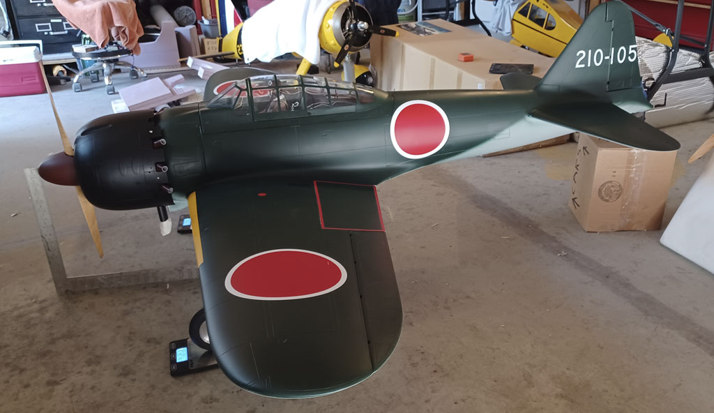
- TopRC Model A6M5 Zero balanced and being weighed on three scales
Wrap up
So we've gone through a really nice build of the TopRC Model 1/5th scale A6M5 Zero. And as I'd hoped, Andy shared a few tips and tricks. The super sounding Saito FG-90R3 engine installation turns out to be relatively straightforward. There was nothing tricky about the servo installation, or the retracts. Point being, for some of you this is a blank canvas and the modeler in you can let loose with further detailing. Like do whatever is in your heart and brings you joy!
Finally, this is the hero of our story, Andy Johnson. He and his superb model of the A6M5 Zero were snapped together at Maloof Air Park in Albuquerque, NM, a magnificent city-owned facility.

- Still pretty sharp for a fella born in 1939
Note; any errors or omissions are mine, and mine only.


